133
Copyright 2017 SolarCity Corporation. All rights reserved.
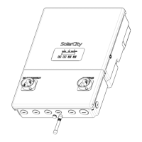
Appendix B - SMART RSD
B.4 - Grounding the SMART RSS
The SMART RSS includes built-in ground fault protection (GFP). No additional grounding is
required if the bracket is securely mounted on the PV track. The bracket also includes a
threaded hold for equipment grounding if the bracket is not used, such as when mounting
the SMART RSS on an interior wall. If you are using a grounding conductor, be sure that it
meets the following minimum size requirements per UL 1741 clause 18:
• Copper: 12AG (3.3mm2)
• Aluminum or copper-clad aluminum: 10AWG (5.3mm2)
The M4 wire-binding grounding screw must have a green-colored head that is either
hexagonal, slotted, or both. You may also use a UL/CSA listed grounding lug/kit to bond to
the rack. Torque the lug according to the manufacturer’s instructions.
B.5 - Warning Label
According to NEC 690.56 (B) and (C), a system that uses an AC or DC disconnect device to
initiate Rapid Shutdown must include a permanent reflective red plaque that includes the
following wording or equivalent in all-capital white lettering with a minimum height of 3/8”
(9.5mm):
PHOTOVOLTAIC SYSTEM EQUIPPED WITH RAPID SHUTDOWN. OPERATION OF THIS SYSTEM
DISCONNECT DEVICE WILL RESULT IN SHUTDOWN OF THE PHOTOVOLTAIC ARRAY IN
ADDITION TO INTERRUPTION OF SYSTEM POWER.
B.6 - Self-Test
SMART RSS devices have an automatic self-test function. Under normal operating condition,
self-testing occur each day during start-up. Failure of the self-test will initiate a continuous
alarm, and the SMART RSS will continue conducting the self-test until successfully
completed. Devices that fail to complete their self-test must be replaced by a qualified
service technician.
Note: The term “PHOTOVOLTAIC” may be replaced with “PV”.