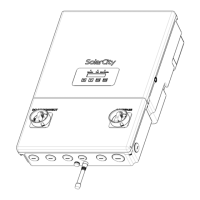
H6 Hybrid Inverter - Installation & Operation Guide
28
Copyright 2017 SolarCity Corporation. All rights reserved.
The wiring box connections themselves are divided into five sections:
• PV interface: See
“PV Interface” on page 28
.
• Battery Pack: See
“Battery Pack Interface” on page 31
.
• Communications: See
“Communications” on page 31
.
• Backup Panel: See
“Backup/Protected Loads Panel” on page 32
.
• AC Grid: See
“AC Grid Point of Interconnection” on page 34
.
3.5.1 - PV Interface
The SolarCity H6 inverter can accommodate up to four (4) PV strings, as follows:
• PV1A(+) and PV1A(-) = MPPT 1, String 1
• PV2A(+) and PV2A(-) = MPPT 2, String 1
• PV1B(+) and PV1B(-) = MPPT 1, String 2
• PV2B(+) and PV2B(-) = MPPT 2, String 2
The SolarCity H6 inverter combines string inputs in parallel into MPPT channels as follows:
• The inputs from PV1A and PV1B combine for MPPT channel 1.
• The inputs from PV2A and PV2B combine for MPPT channel 2.
The two (2) 3/4” conduit holes on the bottom left side of the wiring box are each dedicated
to an MPPT channel. The wiring box also includes an optional 3/4” conduit hole on the left
side. See
Figure 3-13
.
Note: PV1A and PV1B may be combined on the roof such that only two
lines are connected to PV1+ and PV1-. This can also happen with PV2A and
PV2B combined to PV2+ and PV2-. This helps minimize long cable runs
from the strings on the roof to the SolarCity H6 inverter; it is required
when installing multiple strings with an RSD box.
CAUTION: ONLY CONNECT STRINGS WITH IDENTICAL VOLTAGE (SAME
NUMBER AND TYPE OF PANELS) IN PARALLEL. IF STRINGS OF DIFFERENT
VOLTAGES ARE AVAILABLE, THEN YOU MUST USE MULTIPLE MPPT CHANNELS
TO KEEP THE STRINGS INDEPENDENT.
Note: Maintain minimum bending radius requirements, per NEC table
312.6(A).