73
Copyright 2017 SolarCity Corporation. All rights reserved.
6 - User Controls
The LCD display and LED lights provide important information about both the SolarCity H6
inverter and battery pack, including system status, errors, faults, and warnings.
6.1 - Displays and Buttons
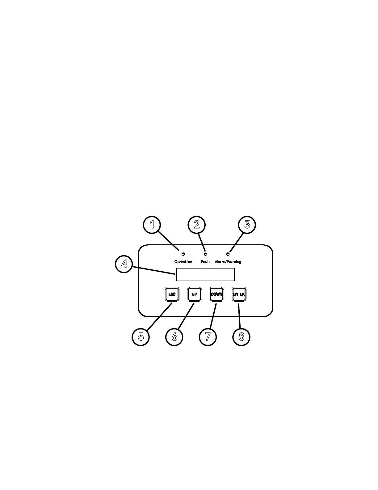
The SolarCity H6 inverter includes the following displays and buttons:
• Three (3) LEDs (one each green, red, and amber) that display basic system status.
• LCD display with two (2) lines of 16 characters each.
• Four (4) push buttons.
Figure 6-1
displays the locations of these items and controls.
Figure 6-1: SolarCity H6 inverter LEDs, LCD display, and buttons
The numbered callouts in
Figure 6-1
correspond to the following:
• Operation LED (1): This LED lights up green to indicate that the SolarCity H6 inverter is
functioning. See
“Status LEDs” on page 75
.
• Fault LED (2): This LED lights up red when a fault condition occurs. See
“Status LEDs” on
page 75
and
“Faults” on page 106
.