131
Copyright 2017 SolarCity Corporation. All rights reserved.
Appendix B - SMART RSD
Route the DC output conductors from the SMART RSS to the SolarCity H6 inverter PV
interface connections as described in
“PV Interface” on page 28
,
“PV Array” on page 37
,and
“PV Connections” on page 63
.If the SMART RSS is installed under the module or on racking,
there must be more than 2.6 inch (65 mm) from the back of the module laminate to the
roof’s surface.
4. Verify that the minimum clearances specified in
“Clearances” on page 129
are present.
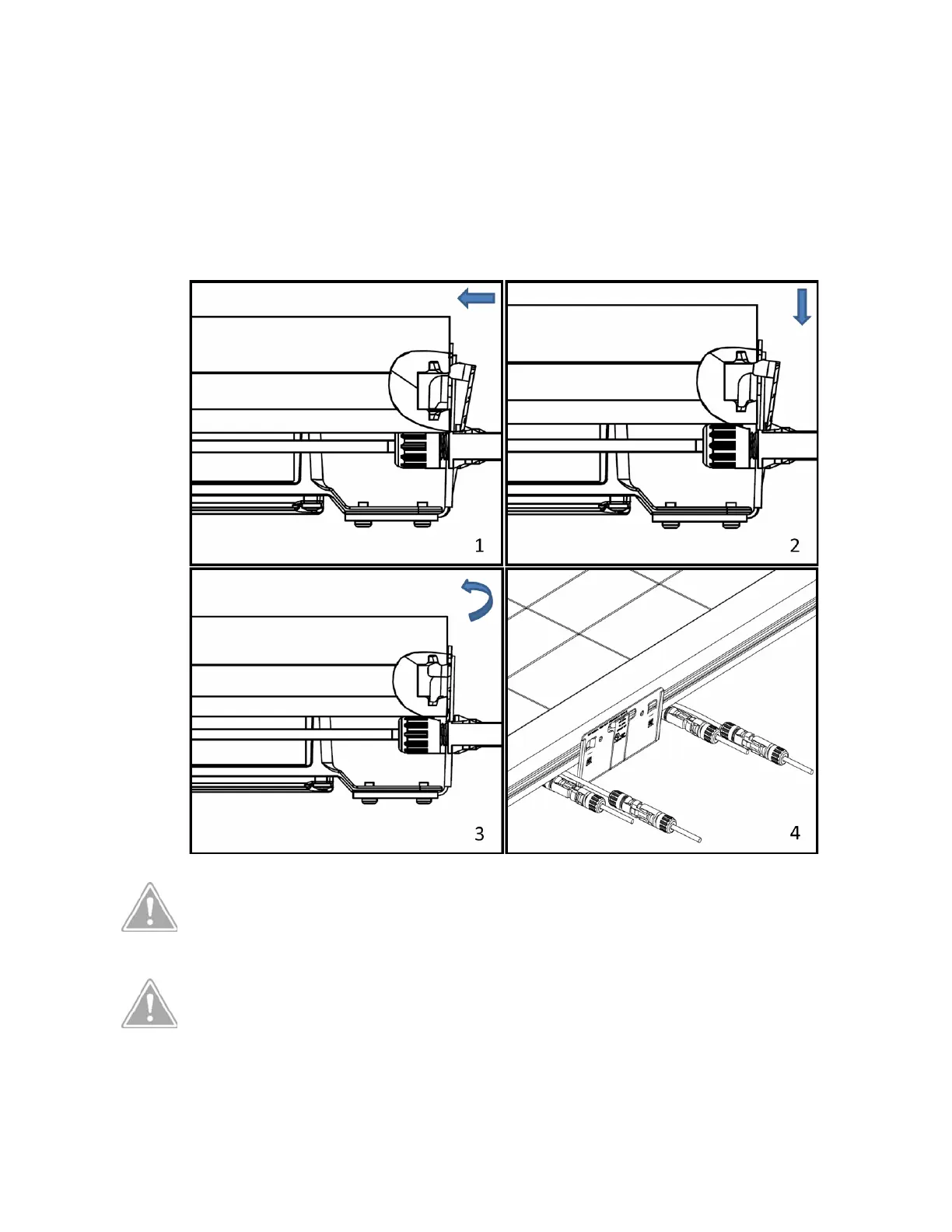
Figure B-3: Installing the SMART RSS (below)
CAUTION: VERIFY THAT THE POLARITY AND VOLTAGE LEVEL ARE CORRECT
WHEN MAKING THE CONNECTIONS. INCORRECT CONNECTIONS MAY
DAMAGE THE SMART RSS AND/OR PV MODULES.
CAUTION: FIELD WIRING CONDUCTORS MUST HAVE AN AMPACITY BASED
ON TABLE 310.16 OF NEC 2014. CALCULATE CIRCUIT SIZING AND CURRENT
ACCORDING TO NEC 2014 ARTICLE 690.8. USE CABLES WITH A MINIMUM
MINIMUM SIZE OF 12AWG AND A MAXIMUM LENGTH OF 100FT (30.5M).