H6 Hybrid Inverter - Installation & Operation Guide
62
Copyright 2017 SolarCity Corporation. All rights reserved.
5.4 - Grounding Connections
Equipment grounding must be connected to the grounding buses within the SolarCity H6
inverter:
• The SolarCity H6 Inverter operates with ungrounded PV source and output circuits in
accordance with NEC 690.35.
• Size the Grounding Electrode Conductor and Equipment Grounding Conductors per 2014
NEC690.47(C)(3)
• PV array grounding conductor(s).
• Battery pack
• Main electrical panel
• Backup electrical panel
The SolarCity H6 inverter is designed and certified to meet the lightning and surge
requirements contained in UL 1741, IEEE 1547, and ANSI/ IEEE 62.41/62.42 AC.
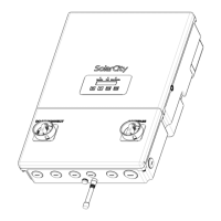
5.5 - Using the Spring Clamp Connectors
The PV array, battery pack, communications, backup panel, and AC grid connections use
spring-clamp connectors.
Figure 5-5
displays the general process of connecting an insulated wire to a spring clamp
connector. The detailed procedure is as follows:
1. Trim at least 3/8” (10mm) off the end of the wire to remove any damaged or corroded
conductor material.
2. Strip 3/4” (20mm) of insulation off the end of the wire, being sure not to break or damage
the conductor(s).
3. Route the wire to the correct connector, as shown in
Figure 1-2
,
Figure 3-11
,
Figure 5-1
,
and in
“Inverter Wiring Box” on page 27
.
WARNING: THE SOLARCITY INPUT AND OUTPUT CONNECTIONS ARE
ELECTRICALLY ISOLATED FROM THE ENCLOSURE. THE INSTALLER IS
RESPONSIBLE FOR INCLUDING SYSTEM GROUNDING THAT COMPLIES
WITH NEC AND ANSI/NFPA 70.
SHOCK HAZARD: ENSURE THAT NO LIVE VOLTAGES ARE PRESENT ON ANY
WIRE THAT YOU ARE CONNECTING TO THE INVERTER.