H6 Hybrid Inverter - Installation & Operation Guide
32
Copyright 2017 SolarCity Corporation. All rights reserved.
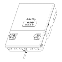
Figure 3-18
displays the communications connections to the inverter wiring box and Fireman
Switch. Actual wire colors may vary from those shown here.
Figure 3-18: Communications connections (colors may vary)
3.5.4 - Backup/Protected Loads Panel
The off-grid/standalone AC output to the protected home loads has two (2) high-voltage
lines labeled BL1 and BL2, plus a neutral line labeled BN. The SolarCity H6 inverter includes a
dedicated 3/4” conduit opening for the backup output connections on the bottom center,
as shown in
Figure 3-19
.
Note: The SolarCity H6 inverter ships with a jumper wire across the
Fireman + and Fireman – connections. If you are not installing a Fireman
Switch with the inverter, then leave the jumper in place; otherwise,
remove it before connecting the lines from the Fireman Switch.