H6 Hybrid Inverter - Installation & Operation Guide
18
Copyright 2017 SolarCity Corporation. All rights reserved.
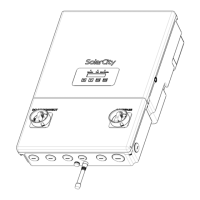
The numbered callouts in
Figure 3-1
correspond to the following:
This list describes the numbered callouts from
Figure 3-1
in detail:
• H6 inverter top section (1): This is the inverter section of the assembly that contains
various electronic components. This section is factory sealed on both the left and right
sides and contains no user-serviceable parts. All wiring to install the inverter and external
connections takes place in the wiring box (#10, below). The top section is fastened to the
wiring box using three (3) M6 nuts. See
“Wiring Box Cover” on page 59
for instructions on
removing and refitting the top section.
• Operation LED (2): This LED lights up green to indicate that the SolarCity H6 inverter is
functioning. See
“Status LEDs” on page 75
.
• Fault LED (3): This LED lights up red when a fault condition occurs. See
“Faults” on
page 106
.
• Alarm/Warning LED (4): This LED lights up amber when an alarm or warning condition
occurs. See
“Alarms” on page 105
and
“Warnings” on page 108
.
• LCD display (5): This display includes two lines with 16 characters per line that show
important messages regarding system status and performance. You can also use this
display to adjust various parameters. See
“LCD Display” on page 76
and
“Menu Structure”
on page 77
.
• ESC button (6): This buttons exits the currently-selected function. See
“Push Buttons” on
page 76
.
• UP button (7): This button either moves up the menu or increases the currently-selected
parameter value. See
“Push Buttons” on page 76
.
• DOWN button (8): This button either moves down the menu or decreases the currently-
selected parameter value. See
“Push Buttons” on page 76
.
• ENTER button (9): This button selects the current menu option or inputs the specified
parameter value. See
“Push Buttons” on page 76
.
1) SolarCity H6 inverter top section 8) DOWN button
2) Operation LED (green) 9) ENTER button
3) Fault LED (red) 10) Wiring box (with cover)
4) Alarm Warning LED (amber) 11) DC Disconnect Switch
5) LCD display 12) AC Bypass Switch
6) ESC button 13) Conduit plugs
7) UP button 14) ZigBee antenna