Installation 1250 Frequency Response Analyzer
2-8 CWB / 1250_Op / Issue 9A
c. Telescopic Slide Inner Members (two off)
The telescopic slides are supplied with inner and outer members, slotted
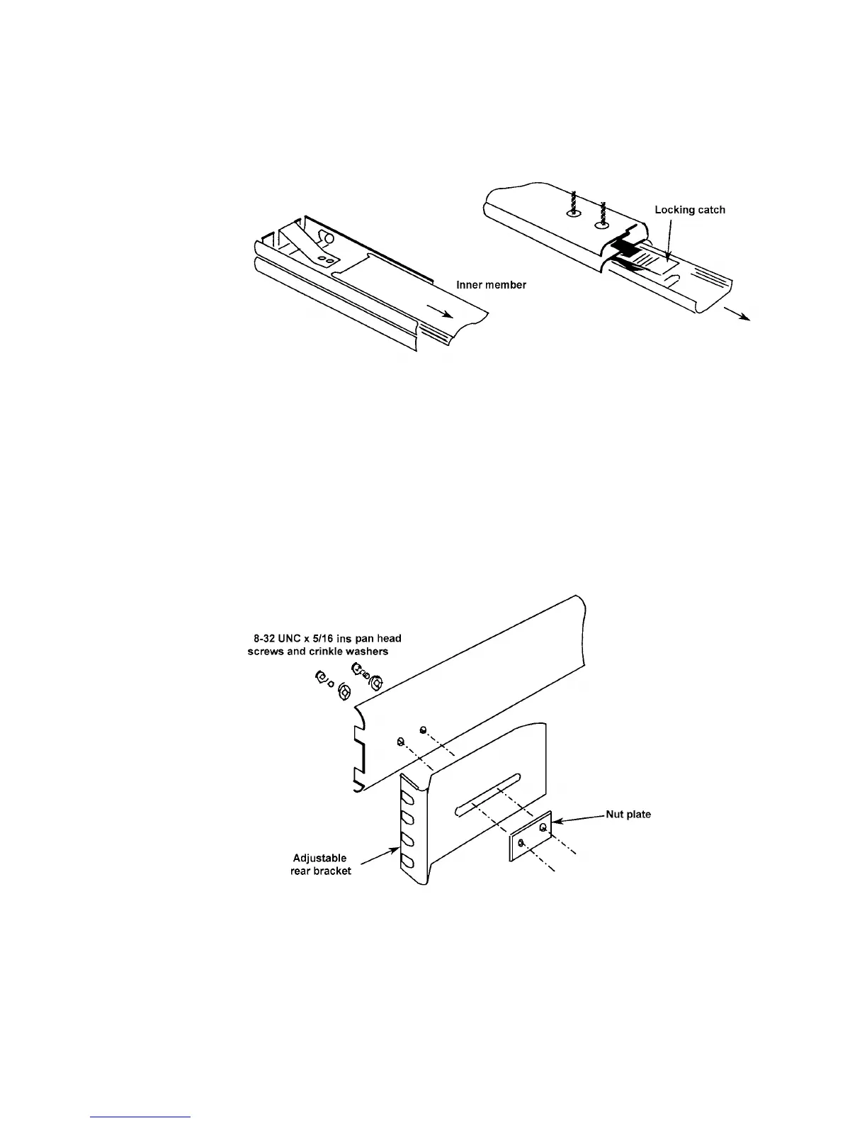
together. Slide out the inner member as shown in Fig. 2.4. depressing the
locking catch at the halfway point.
Figure 2.4 - Separating the inner and outer slide members, prior to fixing
Screw the slide inner members to the mounting bars, using the fourteen M4X6
panhead screws supplied, seven each side.
3. Fit the following items to the telescopic slide outer members, as shown in Fig. 2.5
and 2.6:
c. Adjustable Rear Brackets (two off)
Fit one rear bracket to each outer member, but do not fully tighten the screws
until the 1250 is fitted into the rack (step 6).
Figure 2.5 - Fitting a rear bracket