6-16 Sun Blade 150 Service Manual • June 2002
Caution – Use proper ESD grounding techniques when handling components. Wear
an antistatic wrist strap and use an antistatic mat. Store ESD-sensitive components in
antistatic bags before placing them on any surface.
2. If necessary to provide clearance, remove any long PCI cards from the riser board
connectors.
See Section 8.4.1, “Removing a PCI Card” on page 8-10.
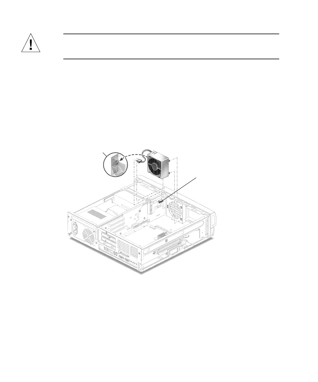
3. Disconnect the fan assembly power cable connector from riser board connector J4
(
FIGURE 6-10).
4. Open the cable retaining clip and remove the fan cable.
5. Press the fan assembly retaining tabs and remove the fan assembly from the
chassis.
FIGURE 6-10 Removing and Replacing the Fan Assembly
6.4.2 Replacing the Fan Assembly
1. Position the fan assembly, ensuring that the fan retaining tabs are aligned with
the chassis retaining slots (
FIGURE 6-10).
2. Press the fan assembly into the chassis slots.
J4 connector
Fan retainer tab