B-2 Sun Blade 150 Service Manual • June 2002
B.1 Power Supply Connectors
There are two power supply connectors on the riser board. The Sun Blade 150 riser
board uses a standard ATX style connector at (J501) and a connector at J505.
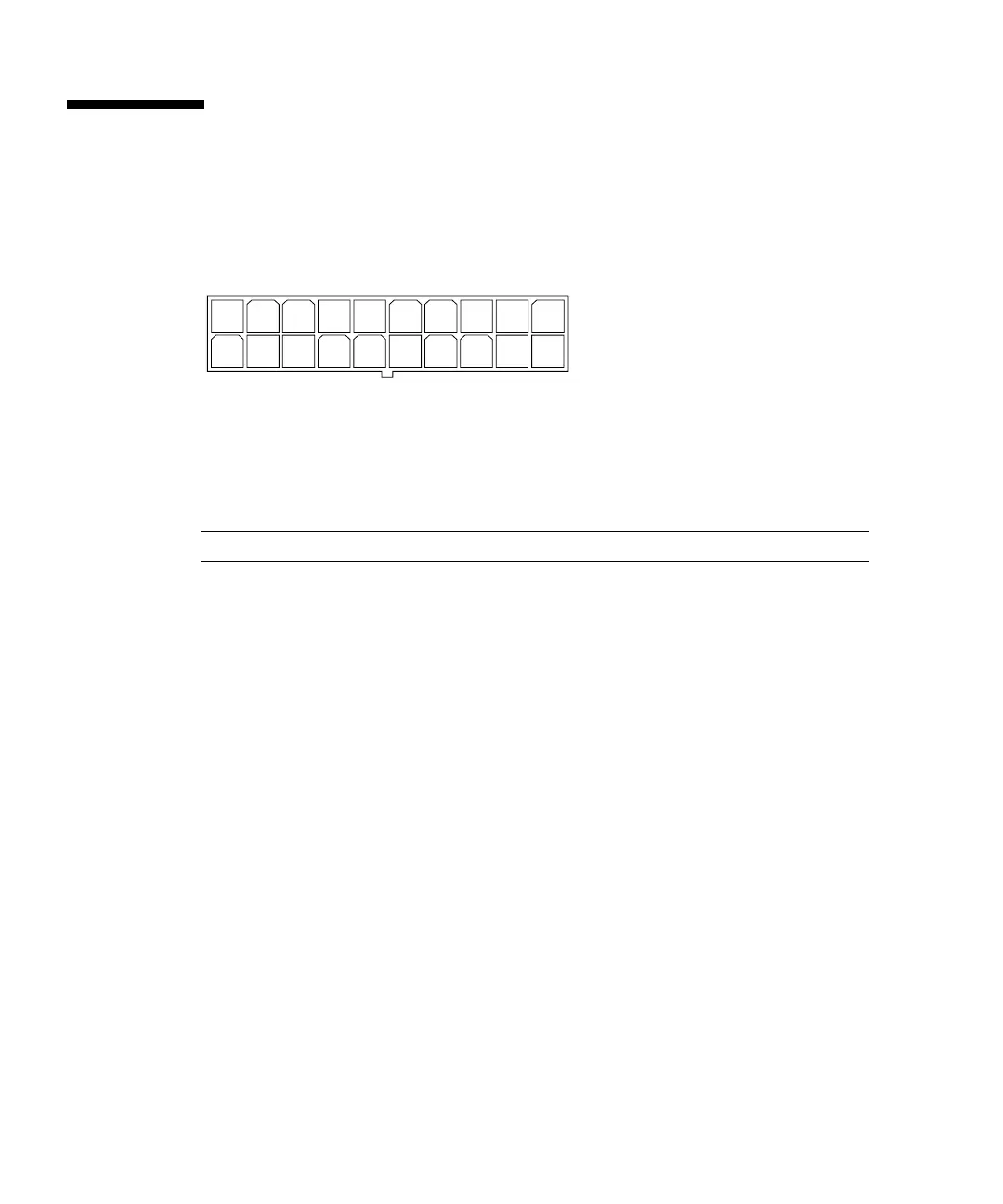
FIGURE B-1 Power Supply Connector J501 Pin Configuration
TABLE B-1 Power Supply Connector J501 Pin Assignments
Pin Signal Description
1 +3.3V +3.3 VDC
2 +3.3V +3.3 VDC
3 Gnd Chassis ground
4 +5V +5 VDC
5 Gnd Chassis ground
6 +5V +5 VDC
7 Gnd Chassis ground
8 PWR_OK Power okay
9 5VSB
10 +12V +12 VDC
11 +3.3V +3.3 VDC
12 -12V -12 VDC
13 Gnd Chassis ground
14 PS_ON Power supply on
15 Gnd Chassis ground
16 Gnd Chassis ground
17 Gnd Chassis ground
110
1120