8-8 Sun Blade 150 Service Manual • June 2002
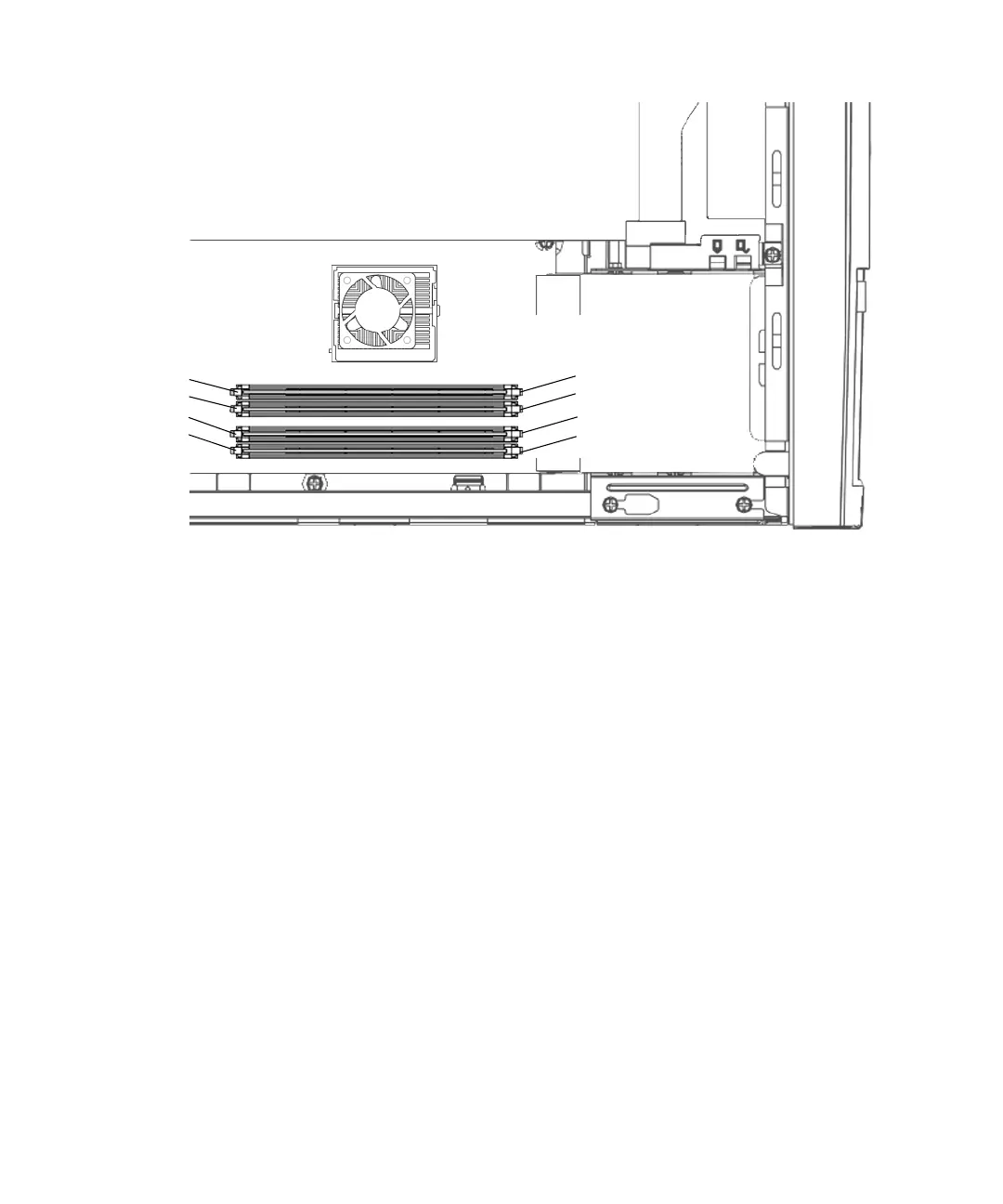
FIGURE 8-4 DIMM Installation Order
2. Locate the DIMM to be removed.
3. Push the ejection levers at each end of the DIMM connector away from the DIMM
(
FIGURE 8-5).
4. Lift the DIMM straight up from the motherboard connector.
5. Place the DIMM on an antistatic mat.
CPU
4
3
2
1
Logical
DIMM0 (U2)
DIMM1 (U3)
DIMM2 (U4)
DIMM3 (U5)
Physical
Connector
Memory Address