6-8 Sun Blade 150 Service Manual • June 2002
Caution – Use proper ESD grounding techniques when handling components. Wear
an antistatic wrist strap and use an antistatic mat. Store ESD-sensitive components in
antistatic bags before placing them on any surface.
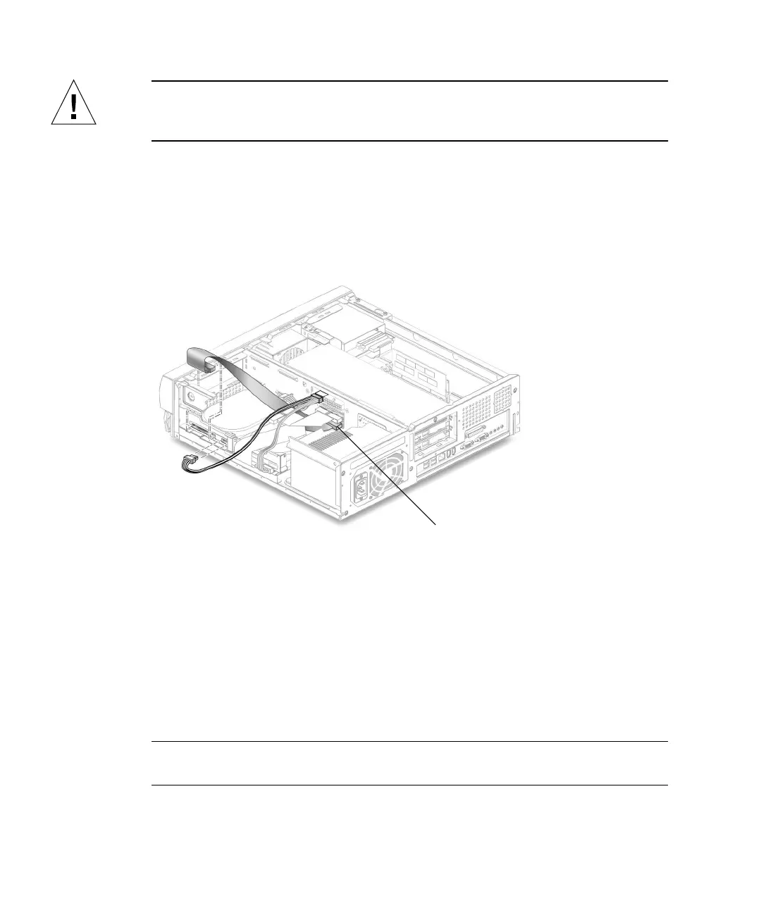
2. Disconnect the secondary IDE cable assembly connector from the following
(
FIGURE 6-5):
■ Secondary hard drive
■ Riser board (J503 is also labeled IDE2)
3. Remove the secondary IDE cable assembly from the chassis.
FIGURE 6-5 Removing and Replacing the Secondary IDE Cable Assembly
6.2.8 Replacing the Secondary IDE Cable Assembly
1. Position the secondary IDE cable assembly into the chassis (FIGURE 6-5).
2. Connect the secondary IDE cable assembly connectors to the following:
■ Secondary hard drive
■ Riser board (J503 is also labeled IDE2)
Note – Ensure that the cable assembly connectors are properly oriented by aligning
the connector keys.
IDE2 (J503)