Chapter 8 Removing and Replacing the Motherboard and Related Components 8-15
1. Using needle-nosed pliers, set the Flash PROM Jumpers, JP1 and JP2.
Flash PROM jumpers JP1 and JP2 are used for reprogramming specific code blocks
and remote programming of the flash PROM.
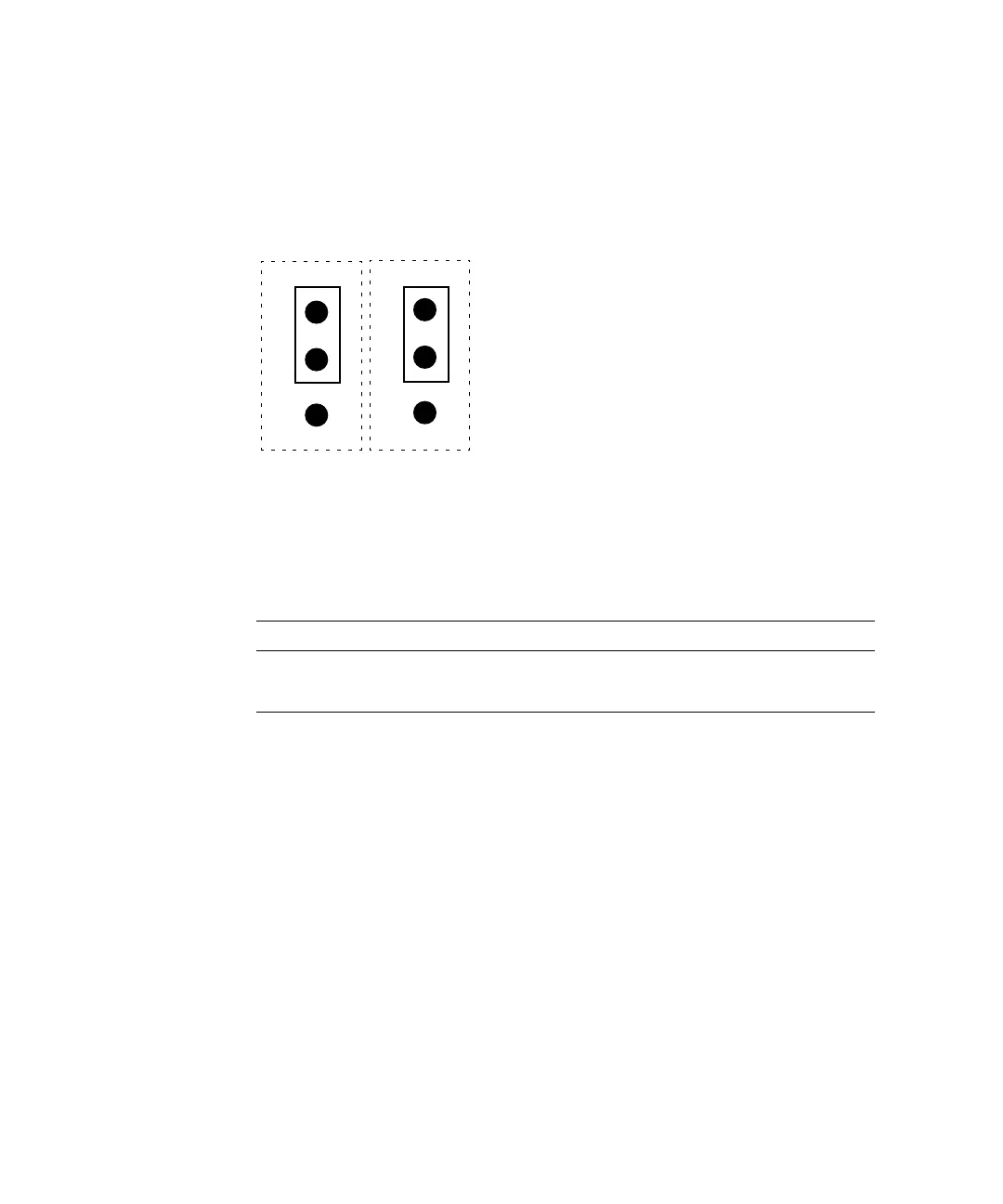
FIGURE 8-8 illustrates the default
JP1/JP2 jumper settings for the flash PROM.
TABLE 8-1 identifies the flash PROM
jumper settings. The default shunt settings of jumpers JP1 and JP2 are 1-2. Placing
the shunt on pins 2 and 3 enables the flash PROM for reprogramming.
FIGURE 8-8 JP1/JP2 Jumper Settings for the Flash PROM
2. Replace the DIMMs.
See Section 8.3.2, “Replacing a DIMM” on page 8-9.
3. Replace the NVRAM/TOD with carrier.
See Section 8.2.2, “Replacing the NVRAM/TOD” on page 8-6.
4. If you removed the CPU or will install a new CPU, see Section 8.1.2, “Replacing
the CPU” on page 8-3.
5. Carefully slide the motherboard tray into the chassis.
6. Position the motherboard connector against the riser board connector and ensure
that the connector keys are properly aligned.
a. Push the motherboard ejection lever toward the chassis to lock the
motherboard into the riser board connector.
TABLE 8-1 Flash PROM Jumper Settings
Jumper Pins 1-2 Select Pins 2-3 Select Default Jumper on Pins
JP1 To onboard PROM (default) To ROMBO 1-2
JP2 Disable Enable 1-2
1
JP1
JP2
2
3
1
2
3