6-4 POWER UNIT
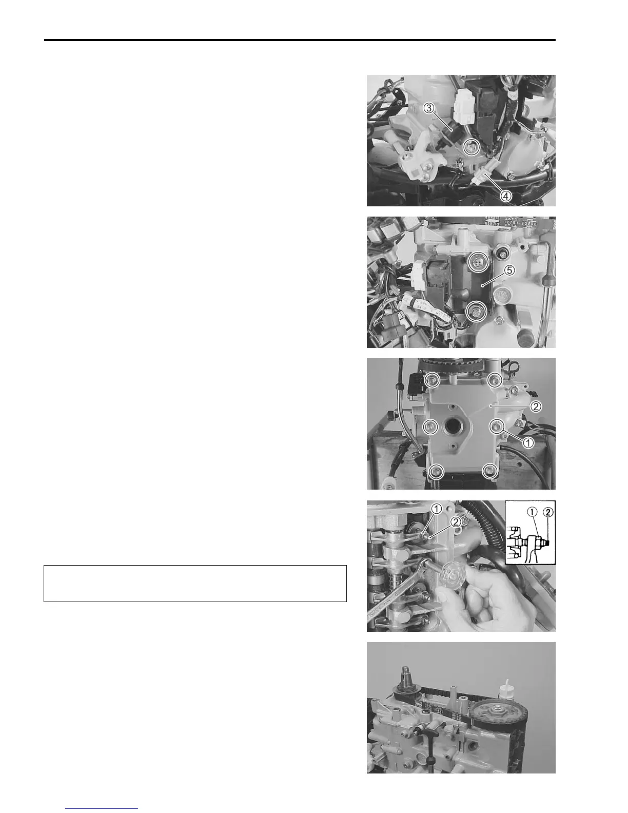
13. Remove bolt, neutral switch/switch bracket 3, then discon-
nect the switch lead wire connector.
Disconnect the caution lamp lead wire connector 4.
14. Remove the two (2) bolts securing electric parts holder 5,
then remove stator base and engine main harness assem-
bly.
15. Remove six (6) cylinder head cover bolts 1, and then cylin-
der head cover 2 and gasket.
16. Loosen all valve adjusting lock nuts 1.
Loosen the four (4) valve adjusting screws 2 fully.
Leave the screws in place.
17. Remove the timing belt. (See page 2-12.)
To prevent valve damage, loosen valve adjusting
screws fully before removing timing belt.
 Loading...