GB.GOLDSKE.160901
24 www.swegon.com
We reserve the right to alter specifi cations without notice.
5.3.1 Airfl ow
See also Section 6.4.1 in which the functions for airfl ow
described in detail.
5.3.1.1 Status
All the relevant values can be read here. Used for performance
checks.
5.3.1.2 Operation level
The functions selected (under Installation) and the min. and max.
airfl ows of each AHU size (see the table below) determine which
values can be set.
Values for airfl ow (l/s, m
3
/s, m
3
/h, cfm), pressure (Pa, psi, in.wc)
or input signal strength (%) can be preset depending on the
function selected.
Low speed
Should always be preset. The value for low speed cannot be
higher than the value for high speed. Low speed can be set to 0,
which means that the AHU is idle.
High Speed
Should always be preset. The value or pressure for high speed
cannot be lower than the value for low speed.
Max. speed
Should always be preset. Used mainly for fi lter calibration. While
fi lter calibration is in progress, the max. speed setting should be
as high as the ventilation system permits without causing any
breakdown. Also used for the pressure regulation, forcing, Heat-
ing Boost and Cooling Boost functions. The value for max speed
cannot be lower than the value for high speed.
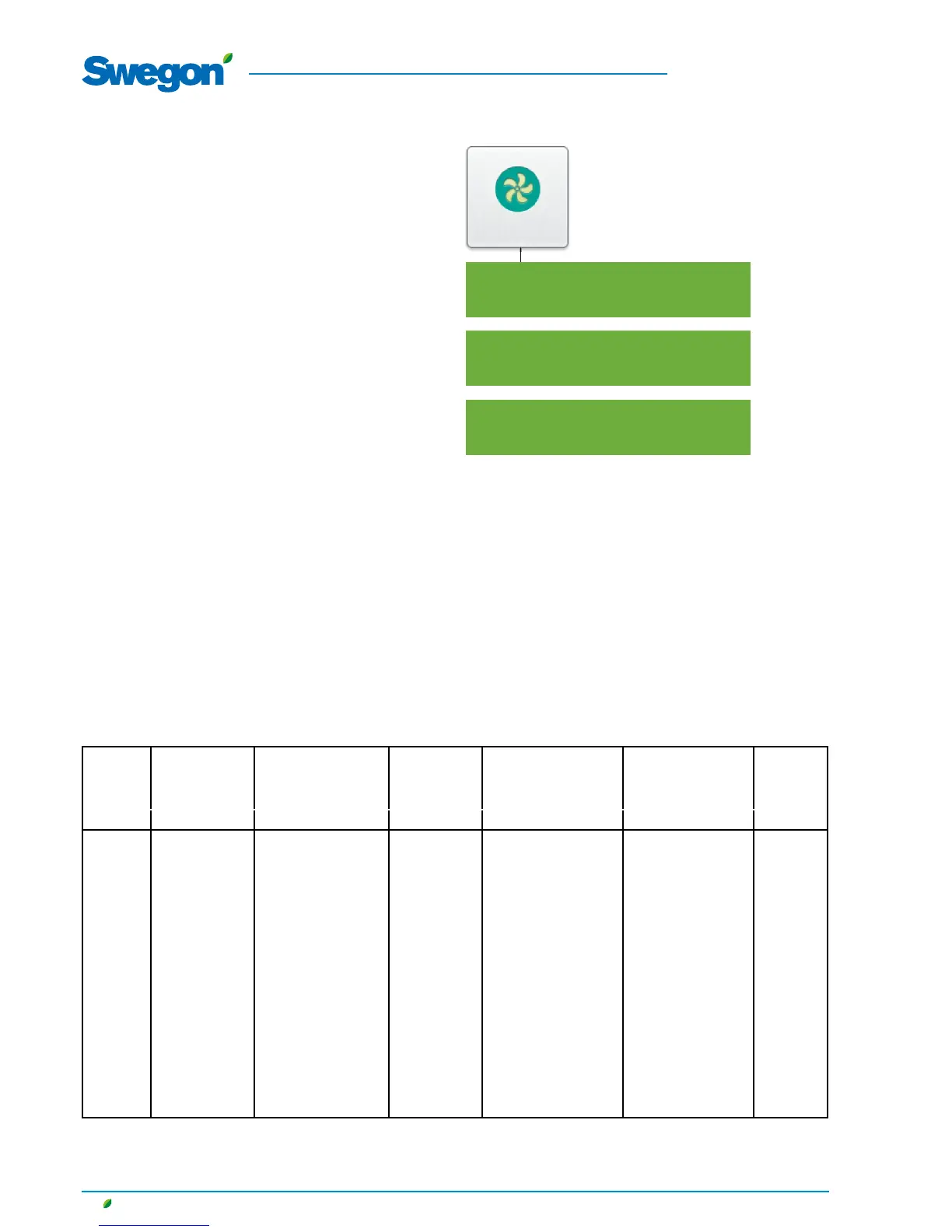
5.3 Functions
Air ow
Status
Operation level
Air adjustment
Min. /Max. speed
Used for the demand control function (the previous section also
applies to max. speed). Preset the lowest and highest permissible
fl ows for each fan. This means that the fans will not operate
outside these limits, regardless the load.
5.3.1.3 Air adjustment
The speed of the fans can be locked for up to 72 hours. When
the function is activated, the speed is locked at the current speed
of operation. This is practical when making airfl ow adjustments
in the duct system and air terminals. The desired period is preset,
but can be interrupted earlier by selecting Stop or by changing
the time setting to 0.
Min./Max. fl ows
1) When adjusting the fl ow, round off the value to the nearest settable step.
2) If pressure regulation is used, the airfl ow can be regulated to zero, however this presupposes a certain static
pressure drop in the ducting (approx. 50 Pa).
3) Cap. variant 1/cap.variant 2
AIRFLOW MIN. FLOW FOR
AIRFLOW REG.,
ALL VARIANTS
2
MAX. FLOW, ONE-PIECE
AHU
ROTARY HEAT EXCH.
(RX)
MAX. FLOW,
ONE-PIECE AHU
PLATE H. EXCH.
(PX)
MAX. FLOW, ONE-PIECE
AHU
COIL H. EXCH. (CX)
MAX. FLOW, SA AND
EA AHU’S (SD)
SMALLEST
STEP
SIZE m
3
/h
1
m
3
/s m
3
/h m
3
/s m
3
/h m
3
/s m
3
/h m
3
/s m
3
/h m
3
/s m
3
/h m
3
/s
GOLD 04 288 0,08 1620 0,45 1620 0,45 2160 0,6 25 0,01
GOLD 05 288 0,08 2340 0,65 2340 0,65 2880 0,8 25 0,01
GOLD 07 288 0,08 2700 0,75 2700 0,75 2880 0,8 25 0,01
GOLD 08 720 0,20 3600 1,00 3600 1,00 4320 1,2 25 0,01
GOLD 11 720 0,20 3960 1,10 3960 1,10 4320 1,2 25 0,01
GOLD 12 720 0,20 5040 1,40 5040 1,40 6480 1,8 25 0,01
GOLD 14 720 0,20 5940 1,65 5940 1,65 6480 1,8 25 0,01
GOLD 20 1080 0,30 7560 2,10 7560 2,10 10080 2,8 25 0,01
GOLD 25 1080 0,30 9000 2,50 9000 2,50 10080 2,8 25 0,01
GOLD 30 1800 0,50 11520 3,20 11520 3,20 14400 4,0 25 0,01
GOLD 35 1800 0,50 14040 3,90 14040 3,90 14400 4,0 100 0,05
GOLD 40 2700 0,75 14040/18000
3
3,90/5,00
3
14040/18000
3
3,90/5,00
3
18000/21600
3
5,0/6,0
3
100 0,05
GOLD 50 2160 0,6 18000 5,00 18000 5,00 20160 5,6 100 0,05
GOLD 60 3600 1,00 23400 6,50 23400 6,50 28800 8,0 100 0,05
GOLD 70 3600 1,00 27000 7,50 27000 7,50 28800 8,0 100 0,05
GOLD 80 5400 1,50 34200 9,50 34200 9,50 43200 12,0 100 0,05
GOLD 100 5400 1,50 39600 11,0 39600 11,0 43200 12,0 100 0,05
GOLD 120 9000 2,50 50400 14,0 50400 14,0 64800 18,0 100 0,05