Chapter 3 Installing the TimeSource 3100
Making Cable Connections
54 TimeSource 3100 User’s Guide 097-72020-01 Revision K – December 2005
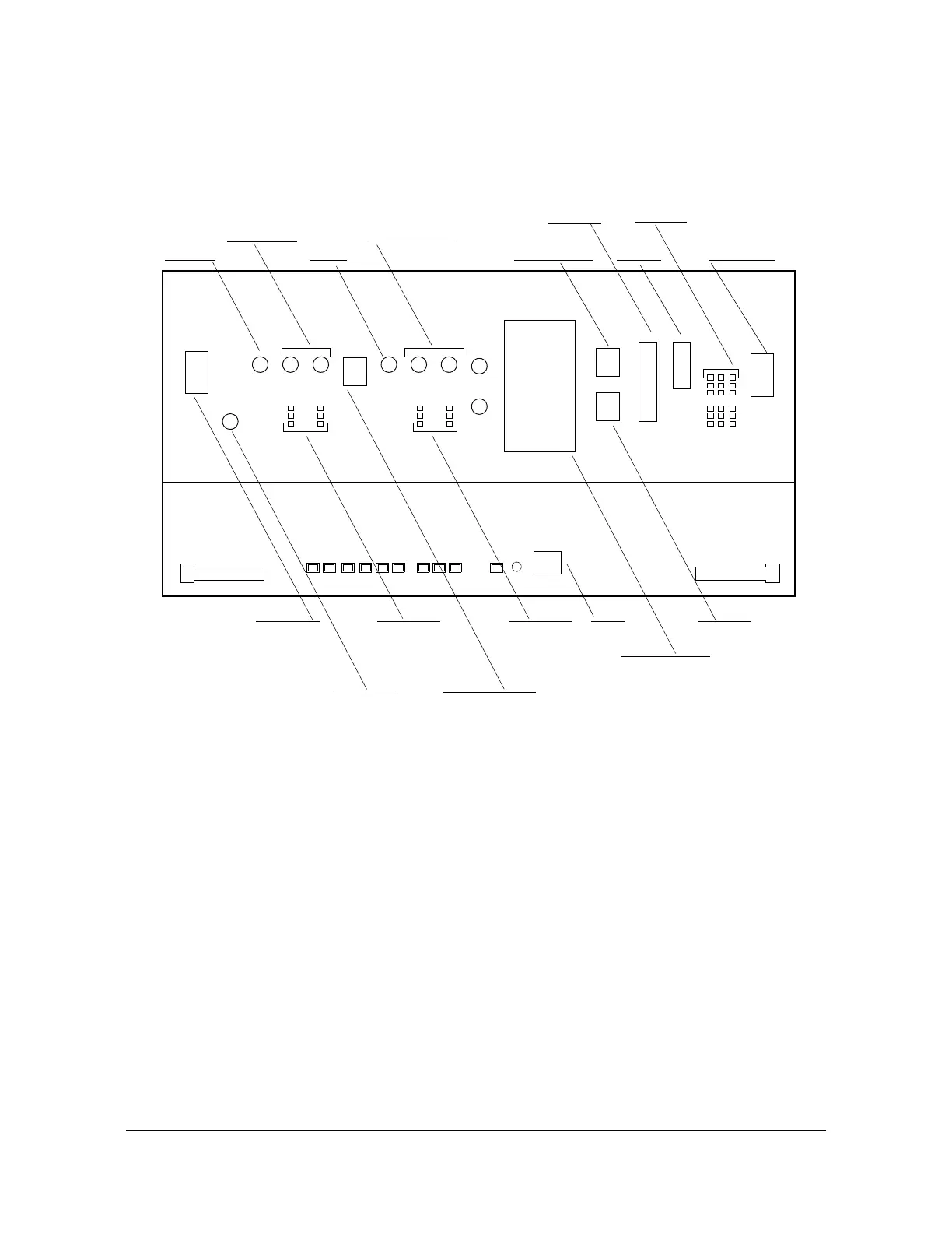
Figure 3-8 shows the connectors on the front panel and connector panel. All
connectors can be located using these illustrations.
Figure 3-8. Connector Panel and Front Panel Connectors
Frame Ground
Frame ground enters through the four-position power terminal blocks labeled TB1
and TB2. Figure 3-9 shows the location of the terminal blocks, and Figure 14 shows
the terminal block connections.
Alarms
Com
port 2
GPS
antenna
input
Battery A
& frame
ground
(TB1)
E1 inputs
A & B
(wire-wrap)
Com
port 1
Time of day
10 MHz
output
E1 outputs
A & B
(BNC)
Battery B
& frame
ground
(TB2)
1 pps
output
Expansion Bus
(Reserved for
future use)
E1 outputs
A & B
(wire-wrap)
E1 inputs A & B
(BNC)
Output Module:
8 E1 outputs (BNC or
wire-wrap) or
4 IRIG-B TOD outputs (BNC) or
2 ESCIU ports (BNC or
wire-wrap) or
8 mixed E1/T1 outputs
(wire-wrap)
Ethernet
Craft
 Loading...