097-72020-01 Revision K – December 2005 TimeSource 3100 User’s Guide 71
Chapter 3 Installing the TimeSource 3100
Making Cable Connections
Connecting to Communication Port 2
To provide an RS-232 link for TL1 command access to the TimeSource 3100,
connect to port 2 at the female 9-pin D connector labeled COM2. See Figure 3-8 for
the location of the connector, and Table 3-6 for the connector pinouts.
Note: Pins not listed are reserved for future use.
Connecting Alarm Outputs
Connect the TimeSource 3100 alarms to the office alarm panel at the critical (CR),
major (MJ), and minor (MN) wire-wrap pins. See Figure 3-8 for the location of the
alarm pins, and Figure 3-21 for the connections.
Connect at the upper group of pins (AUD) for audible alarms and at the lower group
of pins (VIS) for visible alarms. Connect the alarm circuit between the NO and C
pins for normally open contacts, or between the NC and C pins for normally closed
contacts.
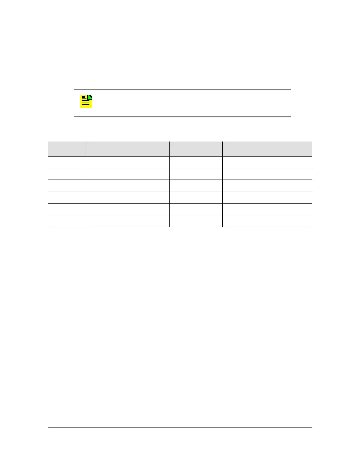
Note: The COM 2 connector transmits data on pin 2 and receives
data on pin 3. Be sure the other equipment receives data from the
transmitting pin, and transmits data to the receiving pin.
Table 3-6. COM 1 Connector Pinout
Pin Signal Abbreviation Direction
2 Transmit data TXD From TimeSource 3100
3 Receive data RXD To TimeSource 3100
5 Signal Ground GND —
6 Data terminal ready DTR From TimeSource 3100
7 Clear to send CTS To TimeSource 3100
8 Request to send RTS From TimeSource 3100
 Loading...