Chapter 3 Installing the TimeSource 3100
Making Cable Connections
68 TimeSource 3100 User’s Guide 097-72020-01 Revision K – December 2005
Connecting the Time of Day Output
If using Time of Day Output, connect the time of day (TOD) output at the female
RJ-45 connector labeled TOD. See Table 3-8 for the connector location, and Table
3-2 for the connector pinouts.
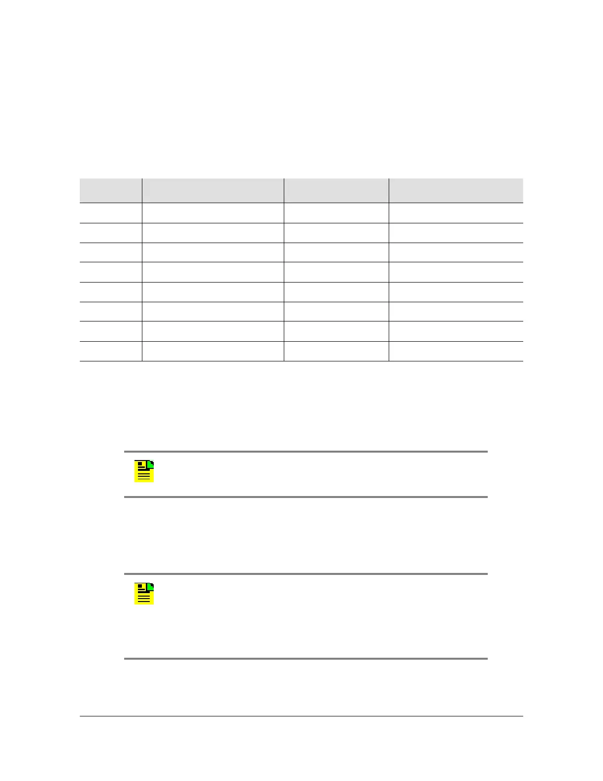
Note: Pins not listed are reserved for future use.
If the device receiving the time code (for example, a Cisco router) accepts an
RS-232 cable instead of an RS-422 cable, follow Procedure D to install the
RJ-45-to-DB-25 TOD converter.
1. Secure the provided mounting plate to the RS-422–to–RS-232 TOD converter
using the two provided screws. The plate may be attached to the top or front of
the converter, depending on the desired surface (for example, a rack or cabinet)
to which the converter will be mounted (see Figure 3-19).
2. Secure the converter to the desired surface, using the slots in the plate and
user-supplied bolts.
Table 3-2. TOD Connector Pinout
Pin Signal Abbreviation Direction
1
1 pps A TOD PPS + From TimeSource 3100
2
1 pps B TOD PPS – From TimeSource 3100
3
12 V power source TOD P12V —
4
Receive data B TOD RXD – To TimeSource 3100
5
Receive data A TOD RXD + To TimeSource 3100
6
Circuit ground TOD GND —
7
Transmit data A TOD TXD + From TimeSource 3100
8
Transmit data B TOD TXD – From TimeSource 3100
Note: Before you perform the following procedure, ensure that the
appropriate Cisco router or NTP type 4 compatible device is installed,
and power applied, per manufacturer's instructions.
Notes:
1. Due to distance constraints, the converter must be placed no
more than 305 m from the TimeSource 3100 Shelf, and no more
than 15 m from the device receiving the time code.
2. The converter dimensions are 7.5 cm by 3.8 cm by 2.5 cm.
3. The mounting plate dimensions are 7.5 cm by 5 cm.
 Loading...