Chapter 3 Installing the TimeSource 3100
Making Cable Connections
58 TimeSource 3100 User’s Guide 097-72020-01 Revision K – December 2005
Connecting E1 or Analog Reference Inputs
E l or analog reference inputs, traceable to an independent Stratum 1 source, can
be used in the output ensemble. Also, the performance of one or two references can
be monitored. In either case, connect reference inputs to the wire-wrap pins or BNC
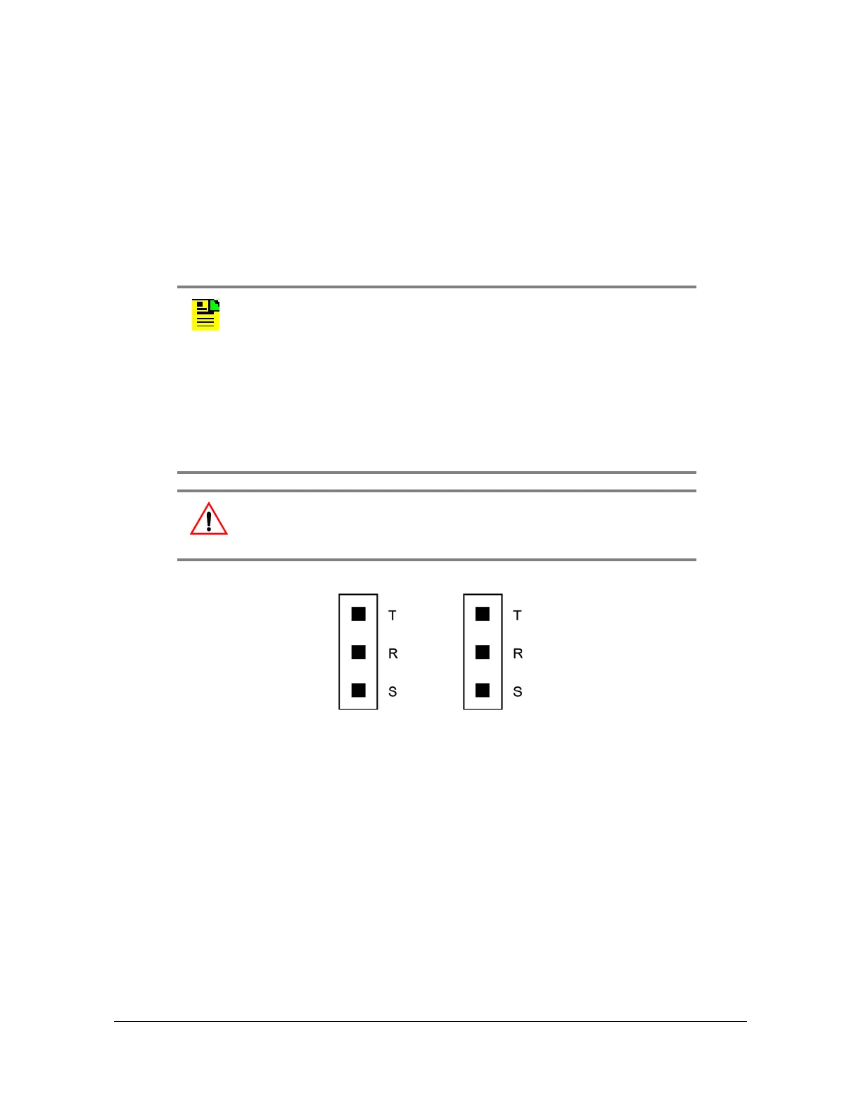
connectors labeled SPAN IN A and SPAN IN B. If using the wire-wrap pins, connect
the tip wire to the pin labeled T, the ring wire to the pin labeled R, and the shield (if
connected at the TimeSource 3100) to the pin labeled S. See Figure 3-8 for the
location of the connectors and pins, and Figure 3-11 for the wire-wrap connections..
Figure 3-11. E1 or Analog Output Wire-Wrap Connections
Connecting Remote Oscillator Inputs
If using the remote oscillator outputs, follow the instructions below.
Refer to Chapter 2, Engineering & Ordering to determine if an isolator kit is required.
Notes:
1. The shield pin is capacitively coupled to ground. Normally, the
shield is grounded at the source. Grounding the shield at both
ends is not recommended.
2. A BNC connector can be used for one output, and a wire-wrap
connector can be used for the other output, but do not use the
BNC and wire-wrap connectors of the same output
simultaneously. For example, a BNC connector can be used for
output A and the wire-wrap pins for output B, but do not use the
output A BNC connector with the output A wire-wrap connector
Warning: To avoid possible equipment damage, do not connect the
El output line directly to a point outside the building. The El output
circuits do not provide lightning protection.

 Loading...