RUN EXCITE: Service & Maintenance Manual - rev. 1.5
Page 4.8
Figure 4.6-9
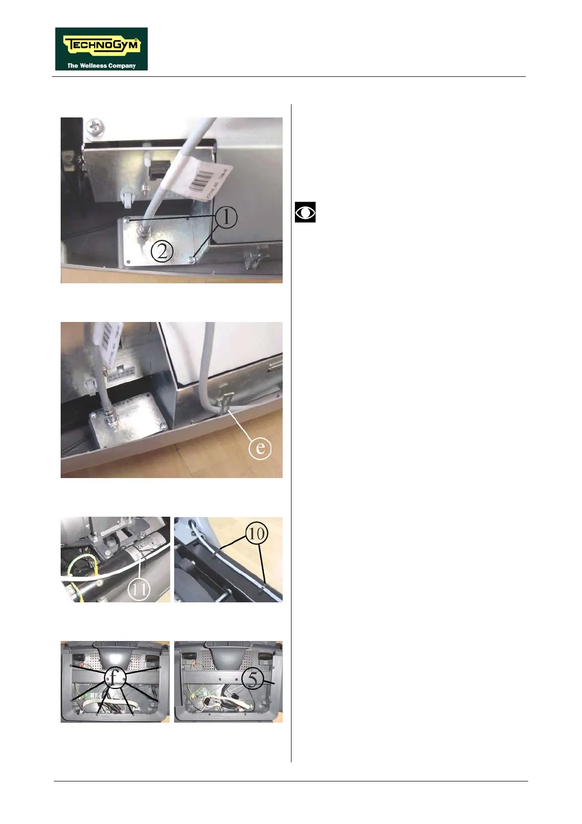
13. Use the two self-tapping screws 1 to fix the
plate 2 on the machine guard, in the position
shown in the figure.
On certain machines it may be necessary
drill the guard at a point coinciding with
the connector, so that it can be accessed
from the outside.
Figure 4.6-10
14. Fix the cable TRM-46 to the electronics box
using the fastener e already fitted on the front
side of the box.
15. Re-connect the three cables, previously
unplugged in point 12, to the electronics box.
Figure 4.6-11
16.
front tube frame as shown in the
17.
e,
nna cable.
18. Reassemble the motor guard.
Use the cable tie 11 to fix the antenna cable
to the
figure.
Insert the two cable clamps 10 into the holes
on the left side of the front machine fram
and use them to secure the ante
Figure 4.6-12
e.
21. Use 5 of the 6 screws to fix the frame 5,
supplied in th
19. Disassemble the machine display from the
control panel.
20. Back off the 6 screws f and remove the
display support fram
e kit.
Continued on following page →
 Loading...


