AGL7 module adjustment procedures
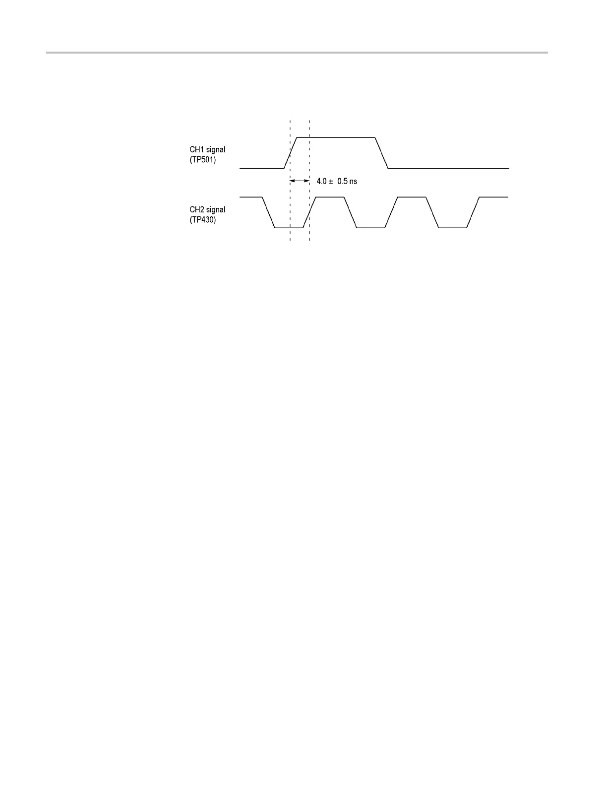
10. Adjust R470 so t
hat the CH2 signal is delayed by 4 ±0.5 ns from the
CH1 signal. (See Figure 4-4.)
Figure 4-4
: Timing relationship between CH1 and CH2 s ignals
11. Move the C
H1 probe from TP501 to TP502.
12. Change the horizontal fine timing of the BLACK 3 ou tput from –7.0 ns to
+7.0 ns a
nd verify that the CH2 signal moves at least 13.5 ns.
13. If the CH2 signal moves less than 13.5 ns, turn R471 to its center position
and the
n perform the following steps:
a. Move the CH1 probe from TP502 to TP501.
b. Set the horizontal fine timing of BLACK 3 output to 0.00 ns.
c. Adjust R470 so that the CH2 signal is delayed by 4 ±0.5 ns from the
CH1 signal.
d. Change the horizontal fine timing of the BLACK 3 output from –7.0 ns to
+7.0 ns and verify that the CH2 signal moves at least 13.5 ns.
If the CH2 signal still moves less than 13.5 ns, turn R471 completely
clockwise and then repeat parts a through d.
14. Change the CH2 probe c onnection from TP430 to TP410.
15. Adjust R472 so that the CH2 signal is delayed by 8 ±0.5 ns from the
CH1 signal.
16. Change the CH1 probe c onnection from TP502 to TP504.
4–10 TG8000 Multiformat Test Signal Generator Service Manual

 Loading...


