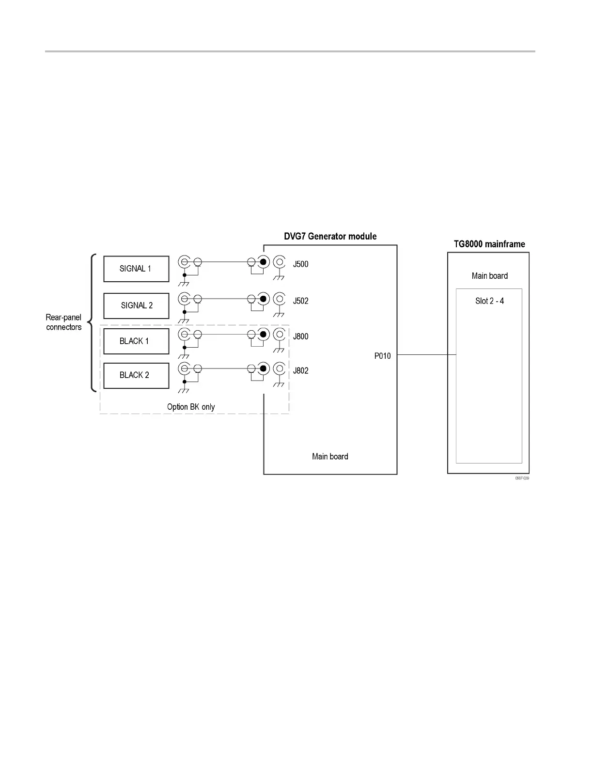
DVG7 module interconnect diagram
DVG7 module in
terconnect diagram
The followin
g figure shows the DVG7 module and how it interconnects with
the TG8000 mainframe.
Diagrams sh
owing mainframe component interconnections, such as power supply
and oscillator, can be found in the Mainframe diagrams section of this manual.
(See page 2-9.)
A block diagram of the DVG7 module is located in the DVG7 module theory
of operation section. (See page 9-10.)
Figure 9-3: DVG7 module interconnect diagram
9–12 TG8000 Multiformat Test Signal Generator Service Manual

 Loading...


