AVG7 module adjustment procedures
To adjust the o
utput offset and gain
Preparation
To perform the output offset and gain adjustment, you must first remove the top
coveroftheT
G8000 mainframe. (See page 2-25, To p cover.)
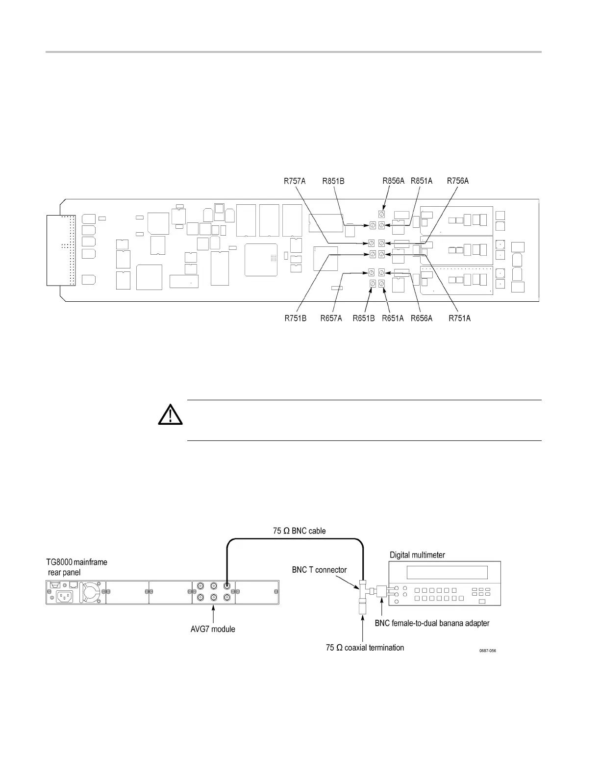
After you have removed the top cover, find the variable resistors on the AVG7
module circuit b oard. (See Figure 6-1.)
Figure 6-1: Location of the variable resistors for the output offset and gain adjustment
Procedure
WARNING. To avoid serious injury, do n ot touch exposed connectors or
components when operating the TG8000 mainframe with the top cover removed.
Dangerous potentials exist at several points within the TG8000 mainframe.
1. Use the 75 Ω BNC cable, BNC T connector, 75 Ω coaxial termination, and
BNC female-to-dual banana adapter to connect the upper CH 1 connector
on the AVG7 Generator module to the INPUT connector on the digital
multimeter. (See Figure 6-2.)
Figure 6-2: Equipment connection for adjusting the output offset and gain
6–4 TG8000 Multiformat Test Signal Generator Service Manual

 Loading...


