ATG7 module adjustment procedures
To adjust chroma gain
Preparation
To perform the chroma gain adjustment, you must first remove the top cover of
theTG8000mainframe. (Seepage2-25,Top cover.)
After you have removed the top cover, find the v ariable resistors on the ATG7
circuit board. (See Figure 5-1.)
Procedure
WARNING. T
o avoid serious injury, do not touch exposed connectors or
components when operating the TG8000 mainframe with the top cover removed.
Dangerous potentials exist at several points within the TG8000 mainframe.
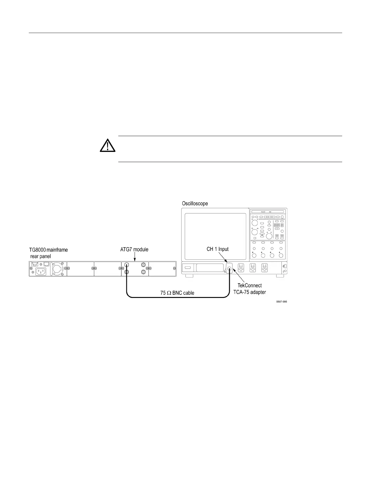
1. Use the 75 Ω BNC cable to connect the SIGNAL c onnector on the ATG7
Generator module to the CH 1 connector on the oscilloscope. (See Figure 5-3.)
Figure 5-3: Equipment connection for adjusting ATG7 chroma gain
2. Select the 75% Color Bars signal for the SIGNAL and BARS outputs as
follows:
a. Press the MODUL E button to display the ATG7 main menu.
b. Press the BARS button to display 75% Color Bars.
c. Press the BACK button to exit the TEST SIGNAL select m enu. The
ATG7 display should show 75% Color Bars.
5–6 TG8000 Multiformat Test Signal Generator Service Manual

 Loading...


