DVG7 module adjustment procedures
Table 9-1: Equipment required for the DVG7 module adjustment procedures (cont.)
Item No. Minimum requirement Recommended equipment
1 m (3 ft.) BNC to BNC 50 Ω
cable
1 Tektronix part number 012-0057-01
75 Ω precision terminator
1
75 Ω ±0.1%
Tektronix part number 011-0102-03
BNC T connector
1 Tektronix part number 103-0030-00
BNC female to dual banana
adapter
1 Tektronix part number 103-0090-00
To adjust the output level
Prepara
tion
To perform the output level adjustment, you must first remove the top cover of
theTG8000mainframe. (Seepage2-25,Top cover.)
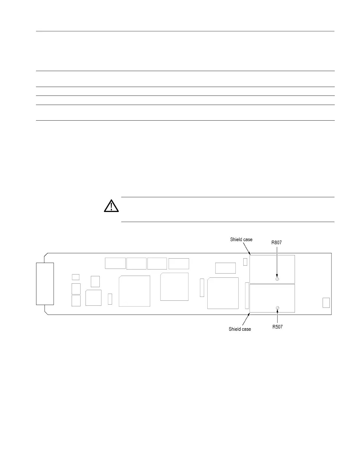
After you have removed the top cover, findthevariableresistorsontheDVG7
circuit board. (See Figure 9-1.)
WARNI
NG. To avoid s erious injury, do not touch exposed connectors or
components when operating the TG8000 mainframe with the top cover removed.
Dangerous potentials exist at several points within the TG8000 mainframe.
Figure 9-1: DVG7 module circuit board
TG8000 Multiformat Test Signal Generator Service Manual 9–3

 Loading...


