Mainframe removal and installation procedures
Access procedure
When you have identified the module to be removed for service, read General
instructions. (See p age 2-20.) Then use the following table to determine which
procedures to use for removing the module. The removal procedures end with
installation instructions.
Ifthemoduleisshownin
Use these procedures
(See Figure 2-6.) Locking line cord (See page 2-24.)
Top cover (See page 2-25.)
Front Panel removal (See page 2-26.)
Front Panel subassemblies (See page 2-28.)
(See Figure 2-7.) Main board (See page 2-33.)
NOTE. Bef
ore performing the Main board, first
remove the locking line cord and top cover using
the procedures listed above.
Power Su
pply module subassemblies(See
page 2-30.)
Locking line cord
1. Assemble the equipment and locate the line cord: Youneednoequipment.
Locate the line cord in the locator diagram. (See Figure 2-6.)
2. Orient the instrument: Set the TG8000 so its bottom is down on the work
surface and its rear is facing you.
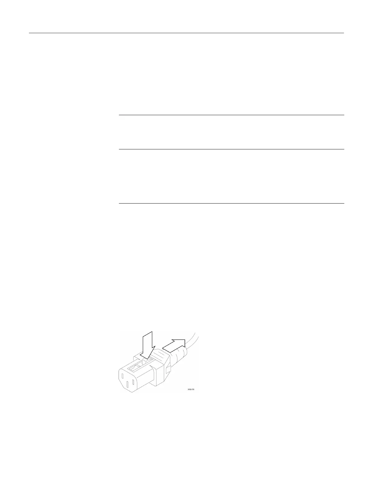
3. Remove the line cord: Find the line cord on the rear panel. The locking cord
has a release latch on the top that must be pressed to remove the cord. Grasp
the plug, press the release latch, and pull the line cord and clamp away.
4. Reinstallation: Inse rt the line cord into the power receptacle on t he TG8000
rear panel until it latches into p lace.
Figure 2-8: Removing the locking line cord
2–24 TG8000 Multiformat Test Signal Generator Service Manual

 Loading...


