AVG7 module adjustment procedures
To adjust interchannel delay
Preparation
To perform the interchannel adjustment, you must first remove the top cover of
theTG8000mainframe. (Seepage2-25,Top cover.)
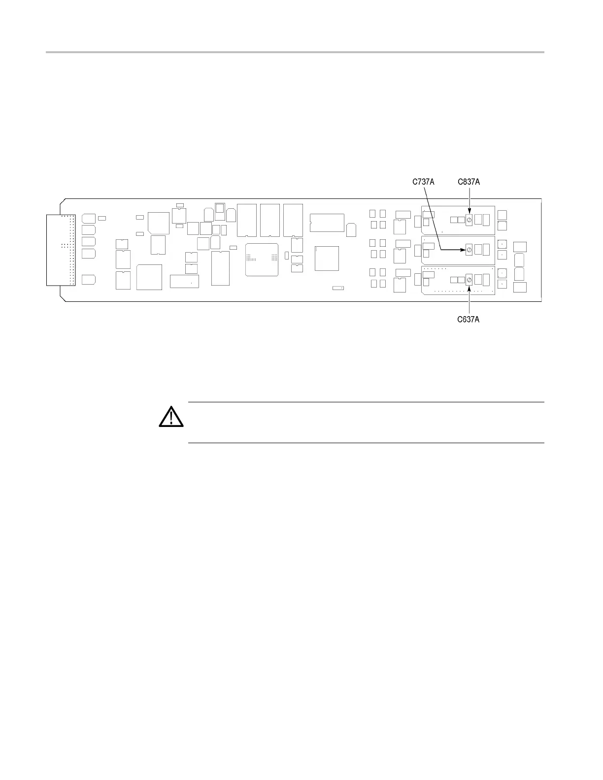
After you have removed the top cover, find the variable capacitors on the AVG7
module circuit b oard. (See Figure 6-9.)
Figure 6-9: Location of the variable capacitors for the interchannel delay adjustment
Proced
ure
WARNING. To avoid serious injury, do n ot touch exposed connectors or
components when operating the TG8000 mainframe with the top cover removed.
Dangerous potentials exist at several points within the TG8000 mainframe.
1. Use the 75 Ω BNCcableandtheTCA7575Ω signal adapter to connect the
upper CH 1 connector on the AVG7 module to the CH 1 input connector on
the oscilloscope. (See Figure 6-10.)
2. Use the 75 Ω BNCcableandtheTCA7575Ω signal adapter to connect the
upper CH 2 connector on the AVG7 module to the CH 2 input connector on
the oscilloscope. (See Figure 6-10.)
3. Use the 75 Ω BNC cable and the 75 Ω feed-through termination to connect the
BLACK 1 connector on the test signal generator to the CH 3 input connector
o
n the oscilloscope. (See Figure 6-10.)
6–14 TG8000 Multiformat Test Signal Generator Service Manual

 Loading...


