AVG7 module adjustment procedures
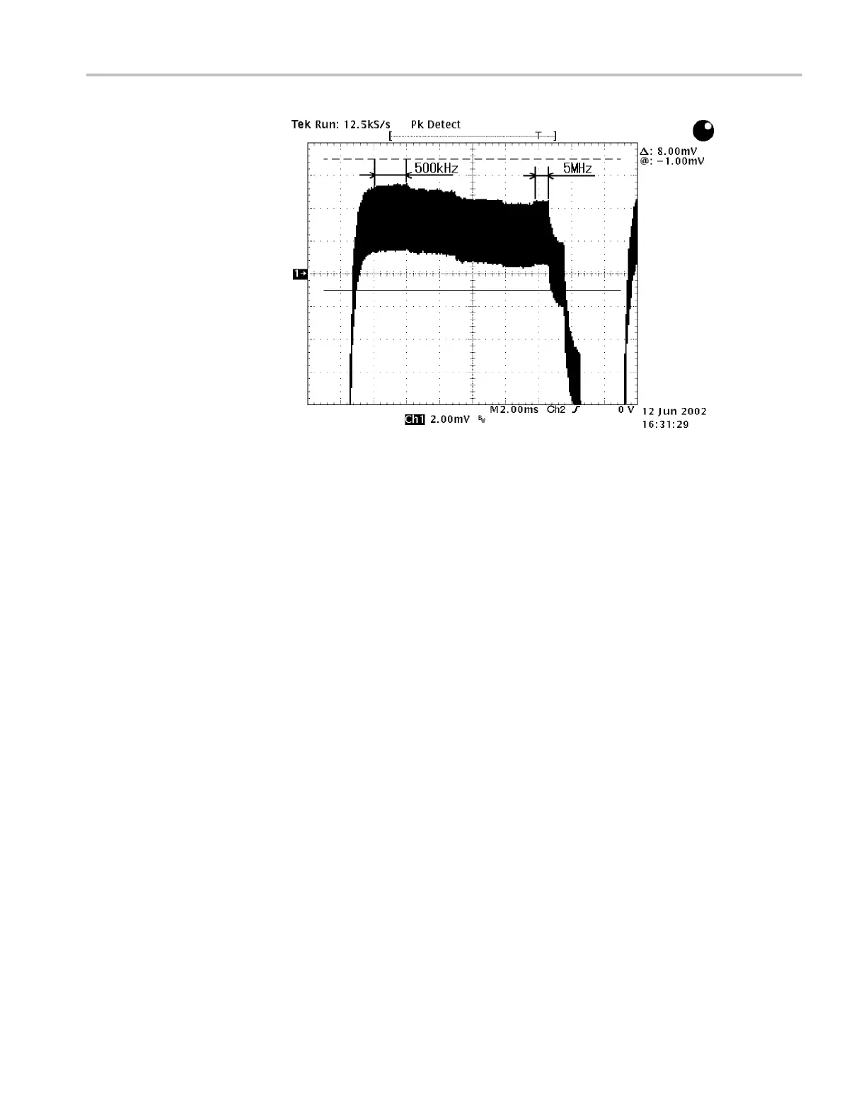
Figure 6-8: Adjusting the signal amplitudes
13. Adjust R835A so that the signal amplitudes from 500 kHz to 5 MHz are
at the same level. (See Figure 6-8.)
14. Readjust C835A and R835A so that the differences of the signal amplitudes
from500kHzto5MHzarewithin2mV.
15. Move the BNC cable from the upper CH 1 connector to the upper CH 2
connector on the AVG7 module.
16. Adjust C735A so that the signal amplitudes of 500 kHz and 5 MHz are at the
same level.
17. Adjust R735A so that the signal amplitudes from 500 kHz to 5 MHz are
at the same level.
18. Readjust C735A and R735A so that the differences of the signal amplitudes
from500kHzto5MHzarewithin2mV.
19. Move the BNC cable from the upper CH 2 connector to the upper CH 3
connector on the AVG7 module.
20. Adjust C635A so that the signal amplitudes of 500 kHz and 5 MHz are at the
same level.
21. Adjust R635A so that the signal amplitudes from 500 kHz to 5 MHz are
at the same level.
22. Readjust C635A and R635A so that the differences of the signal amplitudes
from500kHzto5MHzarewithin2mV.
TG8000 Multiformat Test Signal Generator Service Manual 6–13

 Loading...


