ATG7 module adjustment procedures
d. Press the up (▲)
or down (▼) arrow button to select SELECT OUTPUT.
e. Press the left (◄)orright(►) arrow button to s elect BARS,andthen
press the ENTER button.
f. Press the left (◄)orright(►) arrow button to select PAL, and then press
the ENTER butto
n.
g. Press the left (◄)orright(►) arrow button to select 75% Colour Bar,
and then press the ENTER button.
h. Press the BACK button twice to return to the ATG7 module main menu.
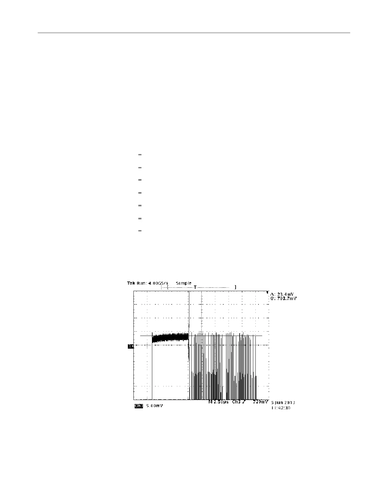
3. Set the oscilloscope controls as follows:
Vertical: 100 mV / div
Sample depth: 100 K
Horizontal: 2 μs/div
Trigger position: 50%
Vert offset: 700 mV
Trigger: 720 mV, rising edge
Hold-off: 63 μs
4. After you see a stable trace on the oscilloscope, change the Vertical setting to
5mV/div.
5. Locate the flat bar followed by the burst packets for yellow and cyan as
shown below.
Figure 5-4: Triggered display for adjusting the ATG7 module chroma gain
TG8000 Multiformat Test Signal Generator Service Manual 5–7

 Loading...


