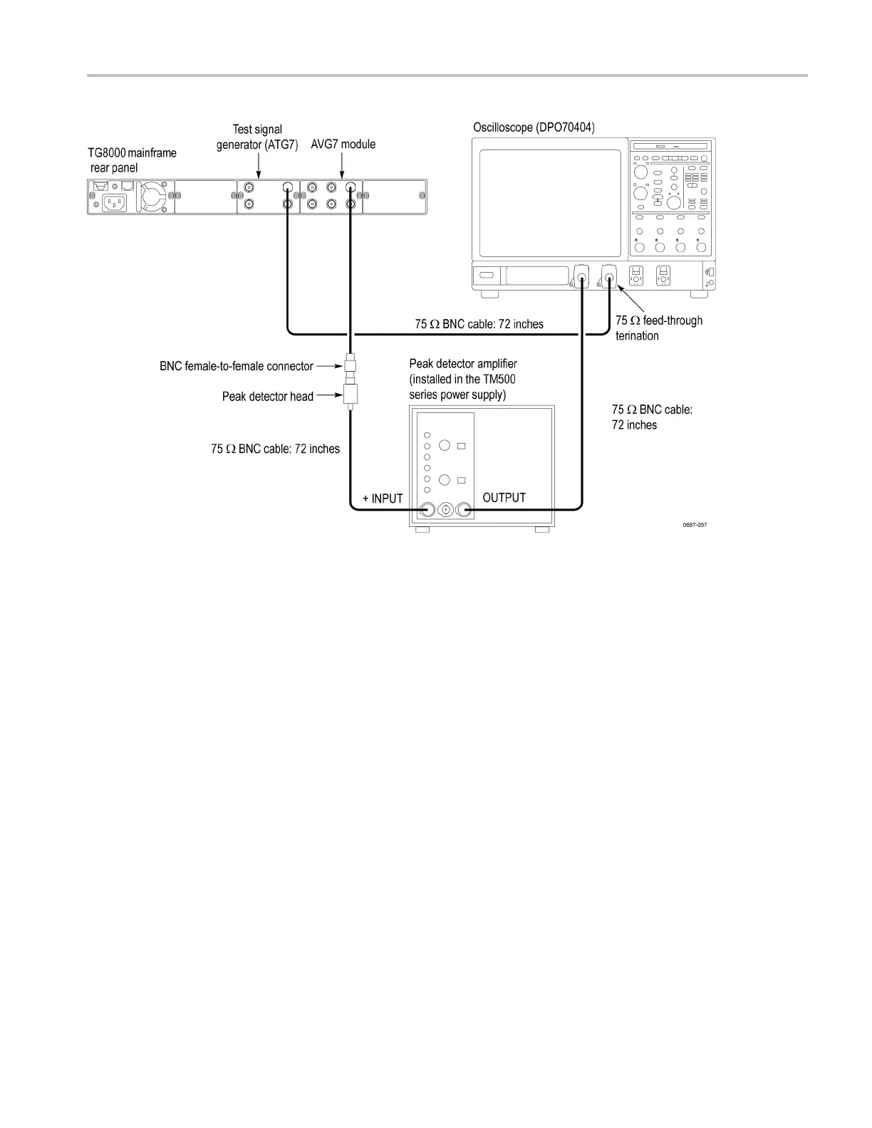
AVG7 module adjustment procedures
Figure 6-7: Equipment connection for adjusting the frequency response
4. Set the oscilloscope settings as indicated below:
Ve rtical scale
CH 1: 2 mV/div, CH 2: 1.00 V/div
Bandwidth
20 MHz (CH 1)
Horizontal scale
2ms/div
Trigger position
10%
Trigger source
CH 2
Trigger type Edge
Acquire menu Peak Detect
5. Set the test signal generator (ATG7 module) settings as indicated below:
Output selection BLACK 1
Signal format NTSC
T
est s ignal
Field Reference
TG8000 Multiformat Test Signal Generator Service Manual 6–11

 Loading...


