AWVG7 module adjustment procedures
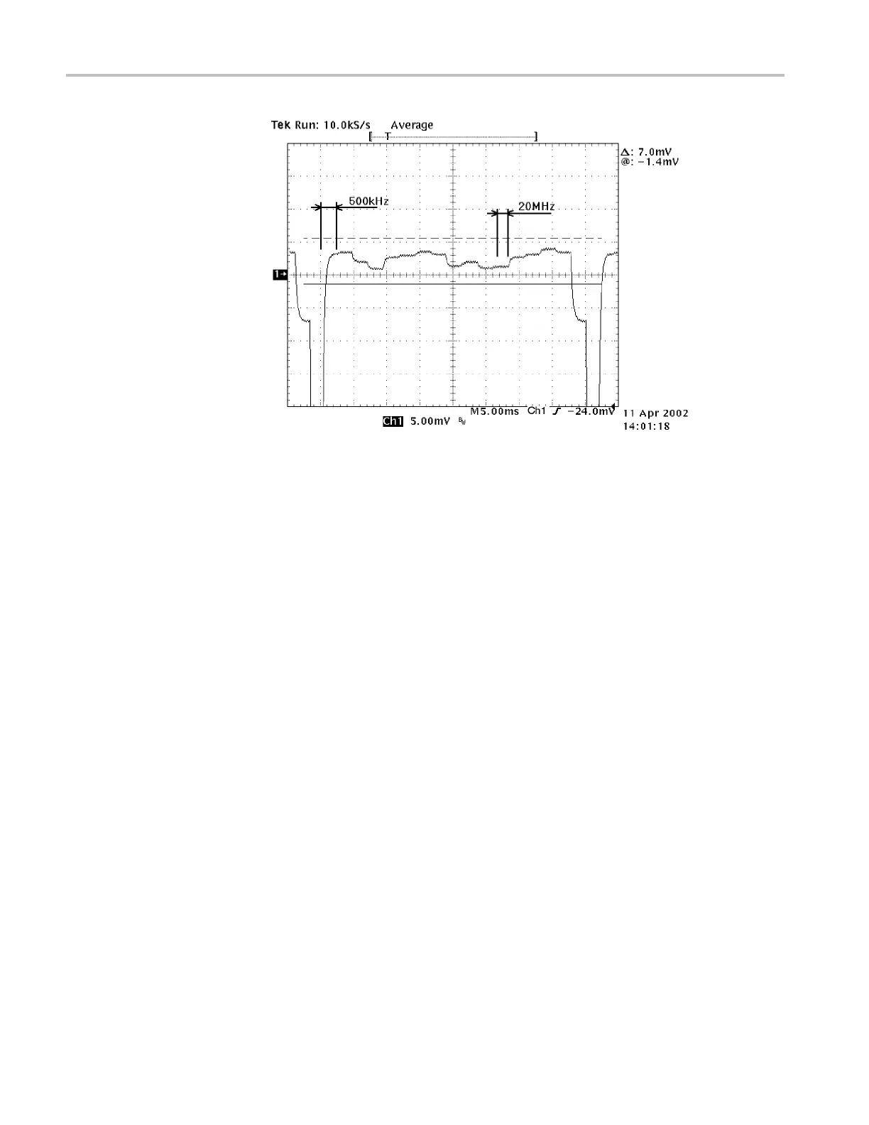
Figure 7-5: Minimizing the amplitude changes
9. Move the BNC cable from the upper CH 1 connector to the upper CH 2
connector on the AWVG7 module.
10. Adjust C704B so that the amplitude changes from 500 kHz to 20 MHz are at
a minimum.
11. Move the BNC cable from the upper CH 2 connector to the upper CH 3
connector on the AWVG7 module.
12. Adjust C604B so that the amplitude changes from 500 kHz to 20 MHz are at
a minimum.
7–10 TG8000 Multiformat Test Signal Generator Service Manual

 Loading...


