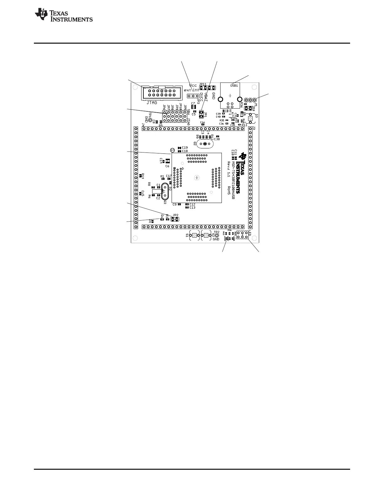
Jumpers LED 1, 2, 3
Open to disconnect LED1, D2, D3LE LE
LED1, D2, D3
LEDs connected to P8.0,
LE LE
P8.1, P8.2
Orient Pin 1 of MSP430 device
Jumpers JP5 to JP10
Close 1-2 to debug in Spy-Bi-Wire mode
Close 2-3 to debug in 4-wire JTAG mode
Jumper JP3
1-2 (int): Power supply from JTAG interface
2-3 (ext): External power supply
Connector JTAG
For JTAG Tool
USB1
USB connector
Connector J5
External power connector
Jumper JP3 to "ext"
Jumper JP2
Open to disconnect LED
D1
LED connected to P1.0
Jumper JP1
Open to measure current
14
1
2
GND
GND
VCC
1 255 10 15 20
26 5030 35 40 45
5175 55606570
76100 80859095
1 2 3
1 2 3
1 2 3
1 2 3
1 2 3
1 2 3
123
1 2 3
1 2 3 4
+
+
J1
J2
U1
www.ti.com
MSP-TS430PZ100AUSB
147
SLAU278Y–May 2009–Revised March 2016
Submit Documentation Feedback
Copyright © 2009–2016, Texas Instruments Incorporated
Hardware
Figure B-75. MSP-TS430PZ100AUSB Target Socket Module, PCB