www.ti.com
MSP-FET
165
SLAU278Y–May 2009–Revised March 2016
Submit Documentation Feedback
Copyright © 2009–2016, Texas Instruments Incorporated
Hardware
B.42 MSP-FET
The MSP-FET is a powerful flash emulation tool to quickly begin application development on MSP430
microcontrollers.
The MSP-FET provides a USB interface to program and debug the MSP430 devices in-system through
the JTAG interface or the pin-saving Spy-Bi-Wire (2-wire JTAG) protocol. Furthermore, the USB interface
can be used for UART backchannel and MSP target BSL communication. UART and I
2
C BSL
communication modes are supported.
The MSP-FET development tool supports development with all MSP430 devices and is designed for use
with PCBs that contain MSP430 devices; for example, the MSP430 target socket boards.
B.42.1 Features
• USB debugging interface to connect a MSP430 MCU to a PC for real-time in-system programming and
debugging
• Software configurable supply voltage between 1.8 V and 3.6 V at 100 mA
• Supports JTAG Security Fuse blow to protect code
• Supports all MSP430 boards with JTAG header
• Supports both JTAG and Spy-Bi-Wire (2-wire JTAG) debug protocols
B.42.2 Release Notes
The MSP-FET is supported by MSP Debug Stack (MSPDS) revision 3.4.0.20 and higher. Observe the
following MSPDS-specific MSP-FET limitations.
B.42.2.1 MSPDS 3.4.0.20 Limitations
• EEM access to F149 and L092 devices is possible only when JTAG speed is set to slow.
• Poly Fuse Blow in Spy-Bi-Wire mode is in beta state and is not officially supported.
• The UART backchannel function is not implemented (even though an additional COM port is shown on
the PC).
B.42.2.2 MSPDS UART Backchannel Implementation
In MSPDS v3.4.1.0 and later, the UART backchannel function is implemented and supported for the MSP-
FET. The baud rates that are supported depend on the target configuration and the debug settings.
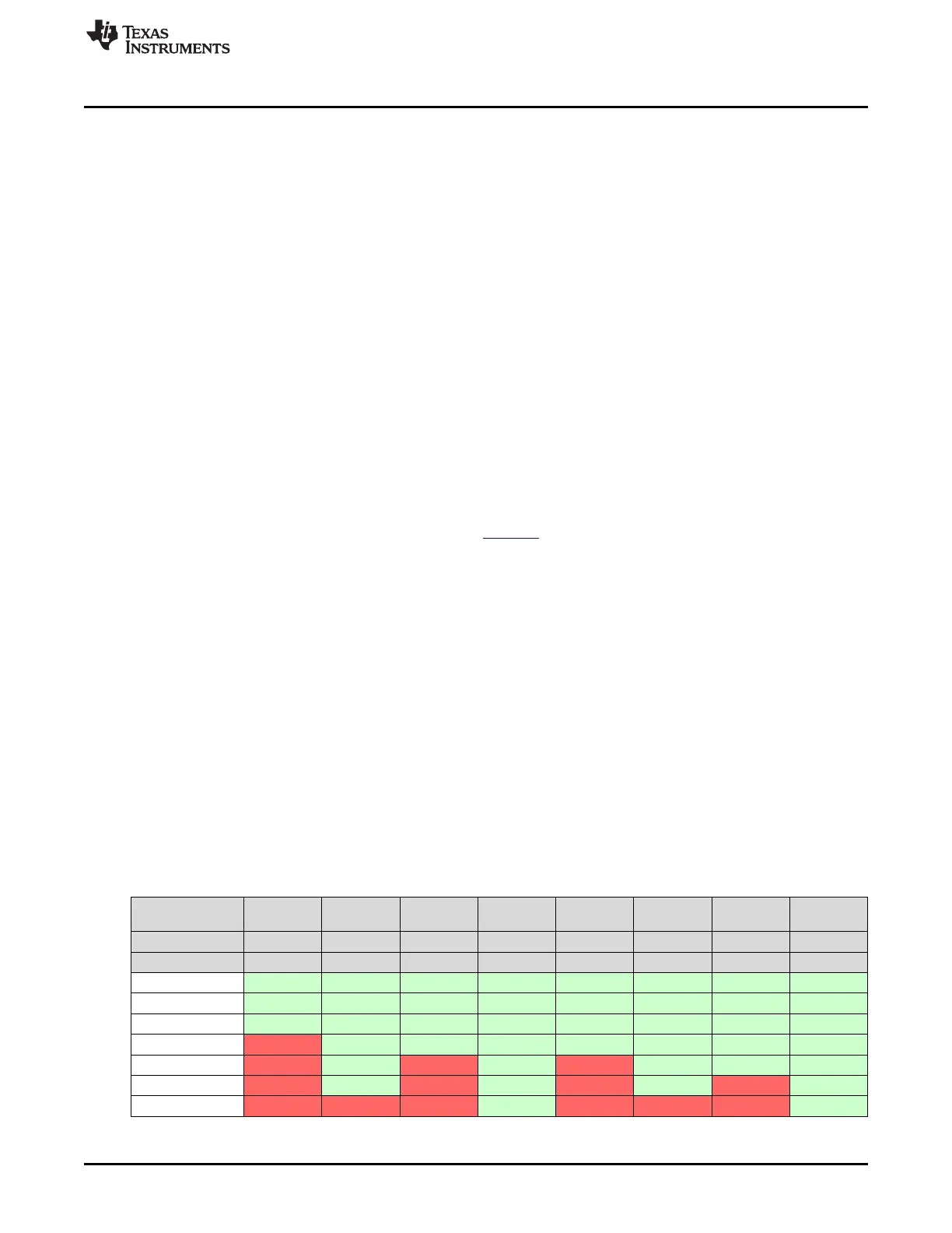
Table B-43 shows which baud rates are supported with certain configuration combinations.
A green cell with ✓ means that the corresponding baud rate is supported without any data loss with the
specified combination of settings.
A red cell with ✗ means that the corresponding baud rate is not supported (data loss is expected) with the
specified combination of settings.
Table B-43. UART Backchannel Implementation
Target MCLK
Frequency:
1 MHz 1 MHz 8 MHz 8 MHz 1 MHz 1 MHz 8 MHz 8 MHz
Debugger: Active Active Active Active Inactive Inactive Inactive Inactive
Flow Control: No Yes No Yes No Yes No Yes
4800 baud ✓ ✓ ✓ ✓ ✓ ✓ ✓ ✓
9600 baud ✓ ✓ ✓ ✓ ✓ ✓ ✓ ✓
19200 baud ✓ ✓ ✓ ✓ ✓ ✓ ✓ ✓
28800 baud ✗ ✓ ✓ ✓ ✓ ✓ ✓ ✓
38400 baud ✗ ✓ ✗ ✓ ✗ ✓ ✓ ✓
57200 baud ✗ ✓ ✗ ✓ ✗ ✓ ✗ ✓
115200 baud ✗ ✗ ✗ ✓ ✗ ✗ ✗ ✓