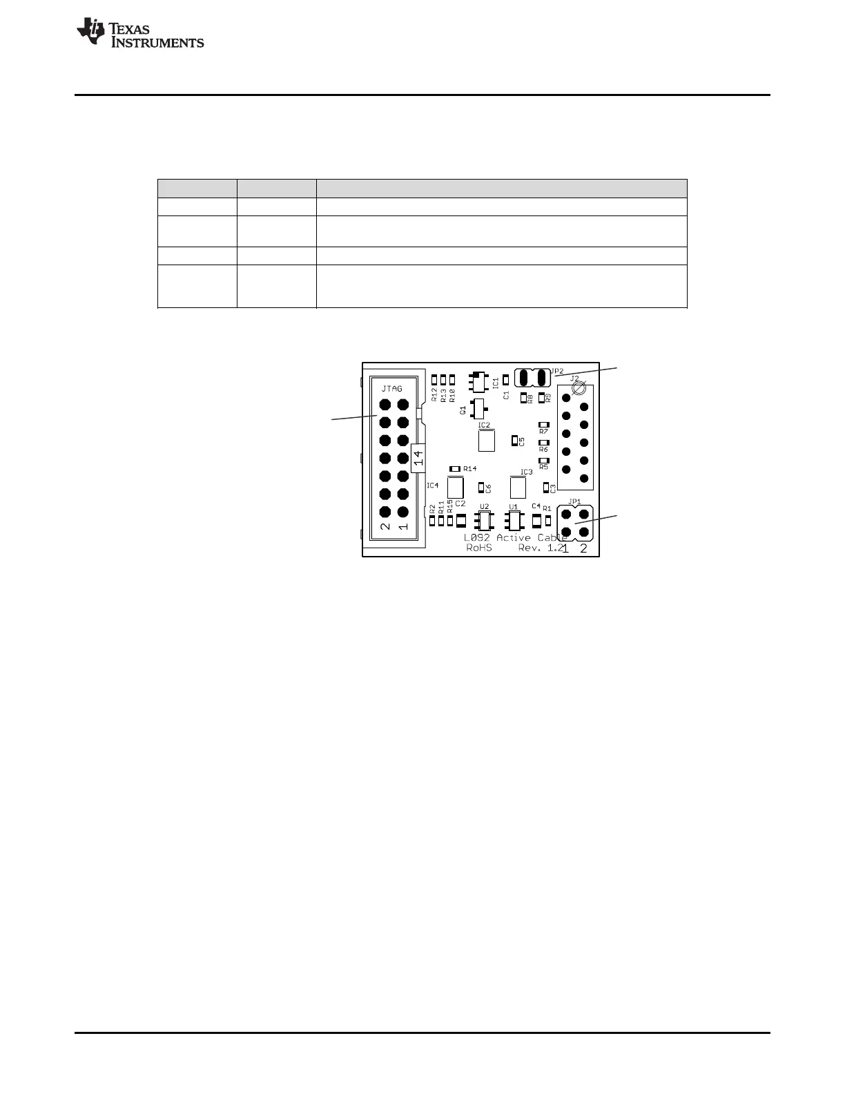
Connector JTAG
For JTAG Tool
JP2
JP1
www.ti.com
MSP-TS430L092 Active Cable
43
SLAU278Y–May 2009–Revised March 2016
Submit Documentation Feedback
Copyright © 2009–2016, Texas Instruments Incorporated
Hardware
Figure B-8 shows the PCB layout for the Active Cable. The following pinning is possible:
• JP1 has two jumpers (Jumper 1 and Jumper 2) that can be set as shown in Table B-4.
Table B-4. MSP-TS430L092 JP1 Settings
Jumper 1 Jumper 2 Description
Off Off The active cable has no power and does not function.
Off On
The active cable receives power from target socket. For this option, the
target socket must have its own power supply.
On Off The active cable receives power from the JTAG connector.
On On
The JTAG connector powers the active cable and the target socket. For
this option, the target socket must not have its own power source, as this
would cause a not defined state.
• JP2 is for reset. For the standard MSP-TS430L092, this jumper must be set. It sets the reset pin to
high and can also control it. Without this jumper on the MSP-TS430L092, reset is set to zero.
Figure B-8. MSP-TS430L092 Active Cable Target Socket Module, PCB