12pF
12pF
GND
100nF
330R
10uF/10V
47K
2.2nF
GND
330R
100nF
GND
GND
GND
green
Ext_PWR
Socket: ENPLAS
Type: OTS-14-065
Vcc
ext
int
to measure supply current
DNP
DNP
DNP
DNP
DNP
JTAG ->
SBW ->
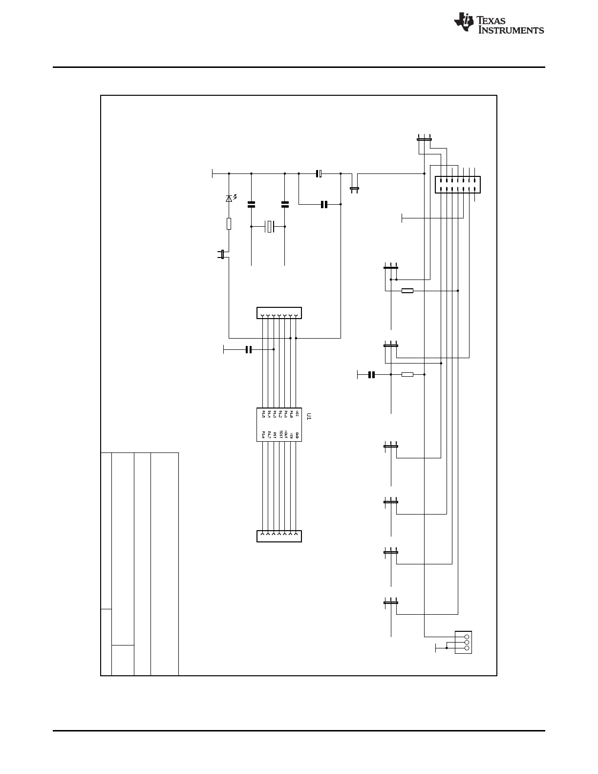
JTAG-Mode selection:
4-wire JTAG: Set jumpers J7 to J12 to position 2-3
2-wire "SpyBiWire": Set jumpers J7 to J12 to position 2-1
1
3
5
7
9
11
13
2
4
6
12
14
8
10
JTAG
C2
C1
C5
R3
C7
R5
C8
1
2
3
J3
Q1
8
9
10
11
12
13
14
J2
1
2
3
4
5
6
7
J1
1
2
J4
1
2
J6
J5
1
2
3
R2
C3
J7
1
2
3
J8
1
2
3
J9
1
2
3
J10
1
2
3
J11
1
2
3
J12
1
2
3
1
2
3
4
5
6
7
8
9
10
14
13
12
11
D1
P1.0
P1.3
P1.2
P1.1
XOUT
XOUT
GND
XIN
XIN
VCC
RST/SBWTDIO
RST/SBWTDIO
SBWTCK
TEST/SBWTCK
TEST/SBWTCK
TEST/SBWTCK
VCC430
P1.4/TCK
P1.4/TCK
P1.5/TMS
P1.5/TMS
P1.6/TDI
P1.6/TDI
P1.7/TDO
P1.7/TDO
TDO/SBWTDIO
RST/NMI
TMS
TDI
Date:
7/16/2007 8:22:36 AM
Sheet:
1/1
REV:
TITLE:
Document Number:
MSP-TS430PW14
+
2.0
MSP-TS430PW14 Target Socket Board
MSP-TS430PW14
www.ti.com
36
SLAU278Y–May 2009–Revised March 2016
Submit Documentation Feedback
Copyright © 2009–2016, Texas Instruments Incorporated
Hardware
B.2 MSP-TS430PW14
Figure B-3. MSP-TS430PW14 Target Socket Module, Schematic