MSP-FET
www.ti.com
176
SLAU278Y–May 2009–Revised March 2016
Submit Documentation Feedback
Copyright © 2009–2016, Texas Instruments Incorporated
Hardware
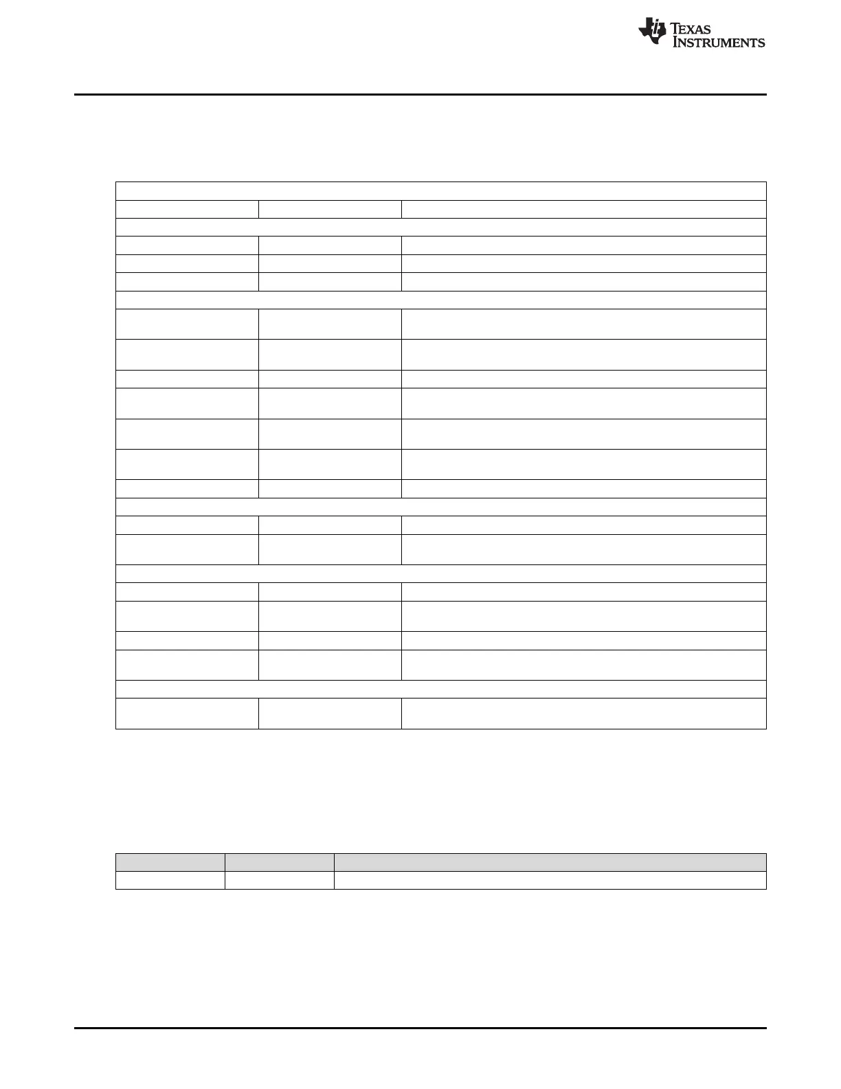
B.42.7 Specifications
Table B-48 shows the physical and electrical specifications of the MSP-FET.
Table B-48. Specifications
Mechanical
Size (without cables) 80 mm x 50 mm x 20 mm
Interfaces
USB interface USB 2.0, full speed
Target interface JTAG 14-pin See Table B-47 for pinout
JTAG cable length 20 cm (max)
JTAG and Spy-Bi-Wire Interface, Electrical
Power supply
USB powered, 200 mA
(max)
Target output voltage
VCC_TOOL
1.8 V to 3.6 V Selectable in 0.1-V steps. VCC_TOOL available from JTAG pin 2.
Target output current 100 mA (max) Current supplied through JTAG pin 2
Target output overcurrent
detection level
160 mA (max)
JTAG signal overcurrent
detection level
30 mA (max) Total current supplied through JTAG pins 1, 3, 5, 7, 8, 10, 11, 12, 13, 14
External target supply Supported (1.8 V to 3.6 V)
Connect external target voltage VCC_TARGET to JTAG pin 4. JTAG
and SBW signals are regulated to external target voltage ±100 mV.
Fuse blow Supported For devices with poly-fuse
JTAG and Spy-Bi-Wire Interface, Timing
JTAG clock speed 8 MHz (max) Protocol speed selectable by software
Spy‑Bi‑Wire clock speed 8 MHz (max)
Protocol speed selectable by software. System limitations due to
external RC components on reset pin (SBWTDIO) might apply.
JTAG and Spy-Bi-Wire Interface, Speed
Flash write speed (JTAG) Up to 20 kB/sec
Flash write speed
(Spy‑Bi‑Wire)
Up to 7 kB/sec
FRAM write speed (JTAG) Up to 50 kB/sec
FRAM write speed
(Spy‑Bi‑Wire)
Up to 14 kB/sec
EnergyTrace™ Technology
Target output current
accuracy
± 2%, ± 500 nA
For target output voltage = 1.8 V to 3.6 V, target output current <75 mA
and USB voltage = 5 V constant during and after calibration
B.42.8 MSP-FET Revision History
Revision numbers are printed on the PCB and are stored in nonvolatile memory in firmware. Table B-49
shows the revision history of the MSP-FET.
Table B-49. MSP-FET Revision History
Revision Date Comments
Revision 1.2 March 2014 Initial release