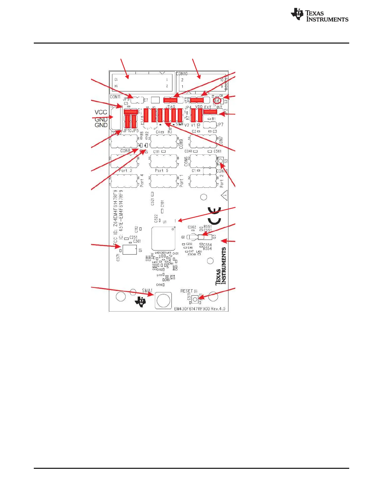
Orient pin 1 of MSP430 device
D1
LED (green) connected
to P1.0 JP5through
Jumpers JP5 and JP10
Open to disconnect LEDs
D2
LED (red) connected
to P3.6 through JP10
Jumpers JP6 and JP8
Close 1-2 for Bypass mode
Close 2-3 for TPS mode
Jumper JP9
TPS status
Connector JTAG
For JTAG Tool
Connector BOOTST
For Bootloader Tool
TPS62730
Jumper JP2
Close INT
: Power supply from JTAG interface
Close EXT: External power supply
Button S2
Connected to P1.7
32-kHz crystal
R554 and R551
Use 0- resistor to make P5.0 and P5.1
available on connector Port 5
W
Button S1
Reset
Jumper JP3
Open to measure current
CON12
External poser connector
Jumper JP2 to "EXT"
Crystal Q1
RF - 26 MHz
SMA1
RF - Signal SMA
Jumper JP1
Close JTAG position to debug in JTAG mode
Close SBW position to debug in Spy-BI-Wire mode
EM430F6147RF900
www.ti.com
162
SLAU278Y–May 2009–Revised March 2016
Submit Documentation Feedback
Copyright © 2009–2016, Texas Instruments Incorporated
Hardware
Figure B-83. EM430F6147RF900 Target Board, PCB
The battery pack which comes with the EM430F6147RF900 kit may be connected to CON12. Ensure
correct battery insertion regarding the polarity as indicated in battery holder.