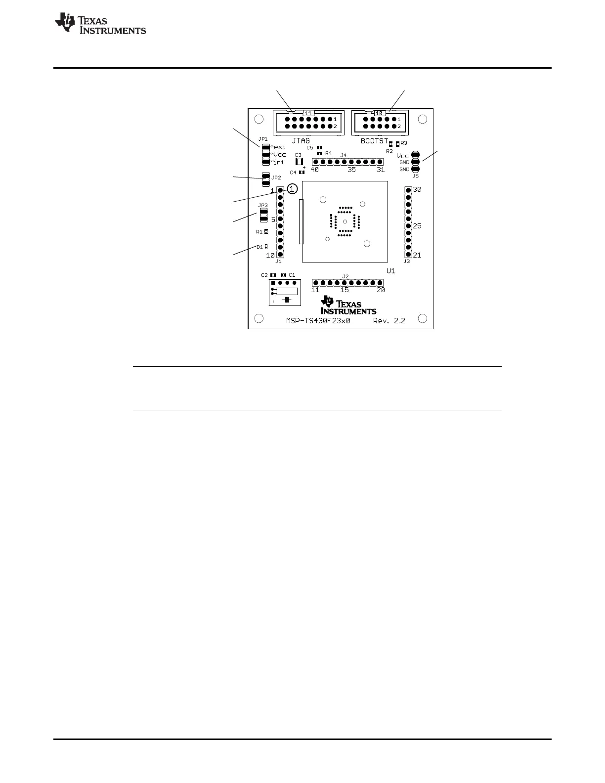
D1
LED connected to P1.0
Connector J5
External power connector
Jumper JP1 to "ext"
Jumper JP3
Open to disconnect LED
Jumper JP2
Open to measure current
Connector JTAG
For JTAG Tool
Connector BOOTST
For Bootloader Tool
Jumper JP1
1-2 (int): Power supply from JTAG interface
2-3 (ext): External power supply
Orient Pin 1 of MSP430 device
www.ti.com
MSP-TS430QFN23x0
71
SLAU278Y–May 2009–Revised March 2016
Submit Documentation Feedback
Copyright © 2009–2016, Texas Instruments Incorporated
Hardware
Figure B-27. MSP-TS430QFN23x0 Target Socket Module, PCB
NOTE: For bootloader use, the BSL connector and only one of the resistors R2 or R3 need to be
populated. If the board is supplied internally, R3 (0 Ω) must be assembled. If the board is
supplied externally, R2 (0 Ω) must be assembled, and R3 must be removed.