CON12
External power connector
Jumper JP2 to "EXT"
GND
GND
VCC
Jumpers JP5, JP10
Open to disconnect LEDs
D2
LED (red) connected
to P3.6 through JP10
D1
LED (green) connected
to P1.0 through JP5
Crystal Q1
RF - 26 MHz
X1
RF - Signal SMA
Button S1
Reset
Push-button S2
Connected to P1.7
Jumper JP1 in Spy-Bi-Wire mode
Q3
Footprint for 32-kHz crystal
R431 and R441
Use 0- resistor to make XIN and XOUT
available on connector Port 5
W
Jumper JP3
Open to measure current
Jumper JP2
Close INT for power supply from JTAG interface
Close EXT to external power supply (CON12)
Connector JTAG
For JTAG Tool
Connector BOOTST
For Bootloader Tool
Jumper JP1
Close SBW position to debug in Spy-Bi-Wire mode
Close JTAG position to debug in 4-wire JTAG mode
EM430F5137RF900
www.ti.com
154
SLAU278Y–May 2009–Revised March 2016
Submit Documentation Feedback
Copyright © 2009–2016, Texas Instruments Incorporated
Hardware
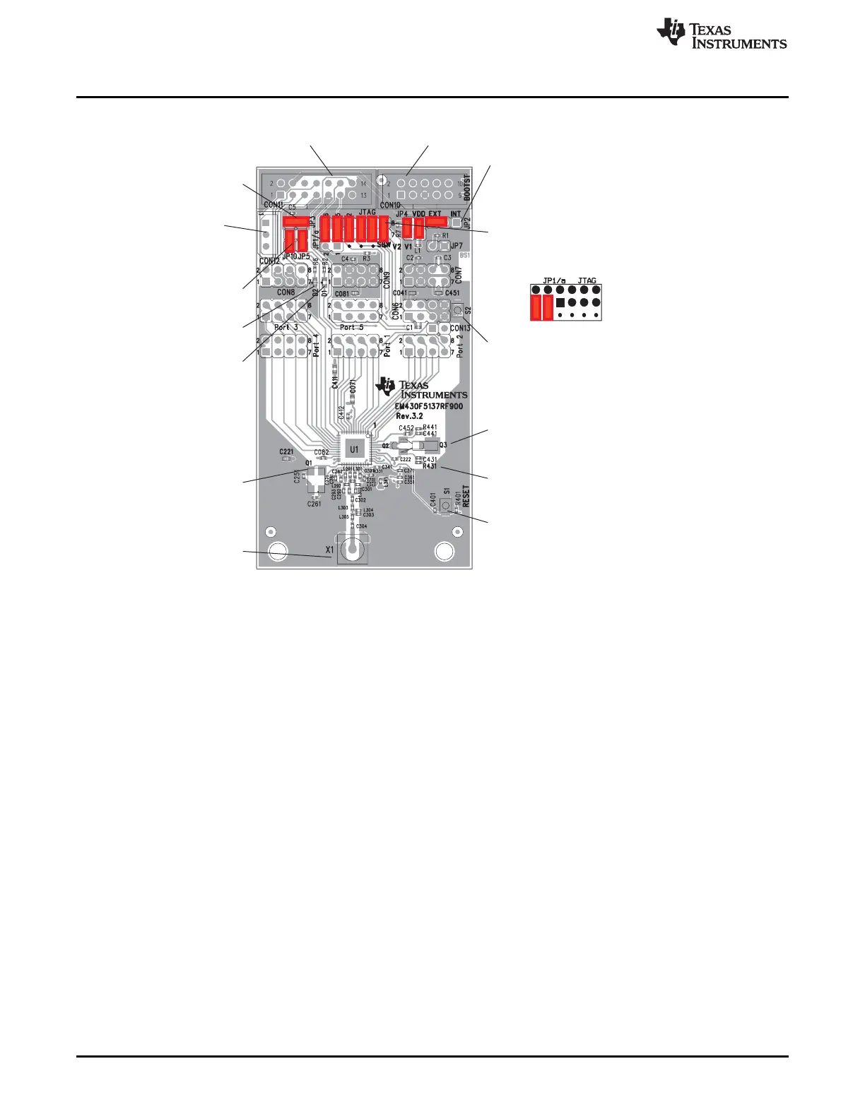
Figure B-79. EM430F5137RF900 Target board, PCB
The battery pack that is included with the EM430F5137RF900 kit may be connected to CON12. Ensure
correct battery insertion regarding the polarity as indicated in battery holder.