www.ti.com
MSP-FET
173
SLAU278Y–May 2009–Revised March 2016
Submit Documentation Feedback
Copyright © 2009–2016, Texas Instruments Incorporated
Hardware
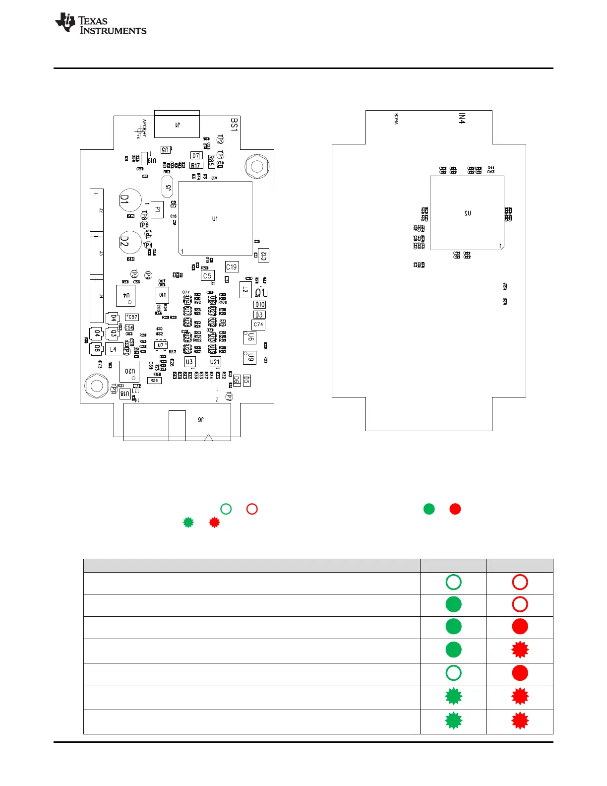
B.42.4 Layout
Figure B-91. MSP-FET USB Debugger, PCB (Top) Figure B-92. MSP-FET USB Debugger, PCB (Bottom)
B.42.5 LED Signals
The MSP-FET shows its operating states using two LEDs, one green and one red. Table B-46 lists all
available operation modes. An or icon indicates that the LED is off, an or icon indicates that
the LED is on, and an or icon indicates that the LED flashes.
Table B-46. MSP-FET LED Signals
Function Power LED Mode LED
MSP-FET not connected to PC, or MSP-FET not ready; for example, after a major firmware
update. Connect or reconnect MSP-FET to PC.
MSP-FET connected and ready
MSP-FET waiting for data transfer
Ongoing data transfer
An error has occurred; for example, target V
CC
overcurrent. Unplug MSP-FET from target,
and cycle the power off and on. Check target connection, and reconnect MSP-FET.
Firmware update in progress. Do not disconnect MSP-FET while both LEDs are blinking.
FPGA update in progress. Do not disconnect MSP-FET while both LEDs are blinking rapidly.