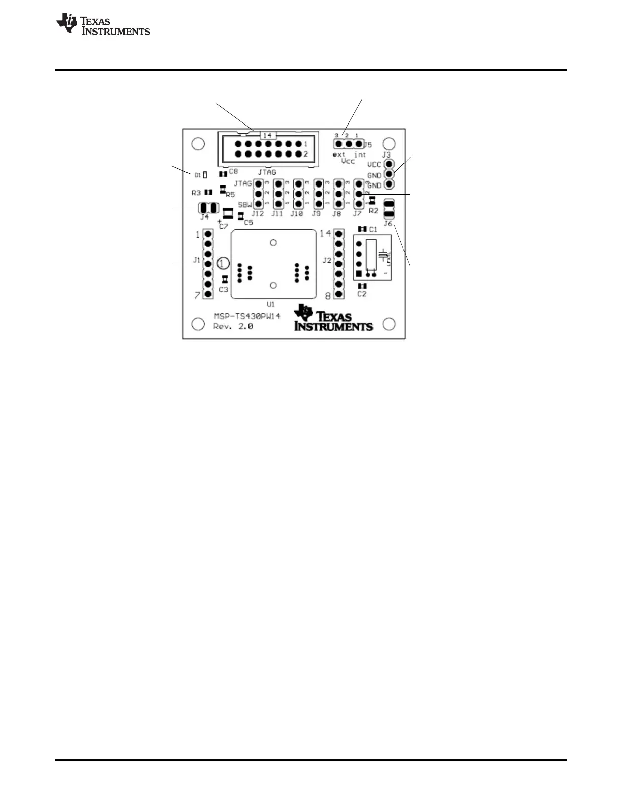
EasyManuals Logo

Texas Instruments MSP430 User Guide

Texas Instruments MSP430
193 pages
To Next Page IconTo Next Page
To Previous Page IconTo Previous Page
Page #37 background imageLoading...
Page #37 background image
Jumper J4
Open to disconnect LED
Orient Pin 1 of MSP430 device
Jumper J6
Open to measure current
Connector J3
External power connector
Jumper J5 to "ext"
D1
LED connected to P1.0
Jumpers J7 to J12
Close 1-2 to debug in Spy-Bi-Wire mode.
Close 2-3 to debug in 4-wire JTAG mode.
Jumper J5
1-2 (int): Power supply from JTAG interface
2-3 (ext): External power supply
Connector JTAG
For JTAG Tool
www.ti.com
MSP-TS430PW14
37
SLAU278YMay 2009Revised March 2016
Submit Documentation Feedback
Copyright © 2009–2016, Texas Instruments Incorporated
Hardware
Figure B-4. MSP-TS430PW14 Target Socket Module, PCB

Table of Contents

Other manuals for Texas Instruments MSP430

Questions and Answers:

Question and Answer IconNeed help?

Do you have a question about the Texas Instruments MSP430 and is the answer not in the manual?

Texas Instruments MSP430 Specifications

General IconGeneral
BrandTexas Instruments
ModelMSP430
CategoryMicrocontrollers
LanguageEnglish

Related product manuals