ELECTRICAL SYSTEM
10E-10
7. With the alternator connected to the wire harness,
turn the key to the ignition position. The alternator
light (L1) should illuminate. If not, check the light
bulb, check for 12V power on the orange wire at
the light socket, perform a continuity test on the
pink wire between the bulb and harness connector
at the alternator.
8. Start the engine. The alternator light (L1) should
extinguish completely. If the alternator light glows
dim and does not shut off completely, check the
terminal connections at the alternator at the BAT
terminal (green wire) and plug in connector
(orange and pink wires). If problems still exist,
check the alternator diodes and voltage regulator.
REGULATOR (U1) TEST
1. Remove the terminal cover to expose the battery
terminal on the alternator.
Figure 10E-3. Alternator
2. Set the multimeter to the 20 Volt DC scale.
3. With the engine off, touch red lead to exposed bat-
tery terminal and black lead to alternator housing.
The multimeter should indicate battery voltage.
4. Repeat step 3 with the engine running. Observed
voltage should be between 13.5 to 15 volts.
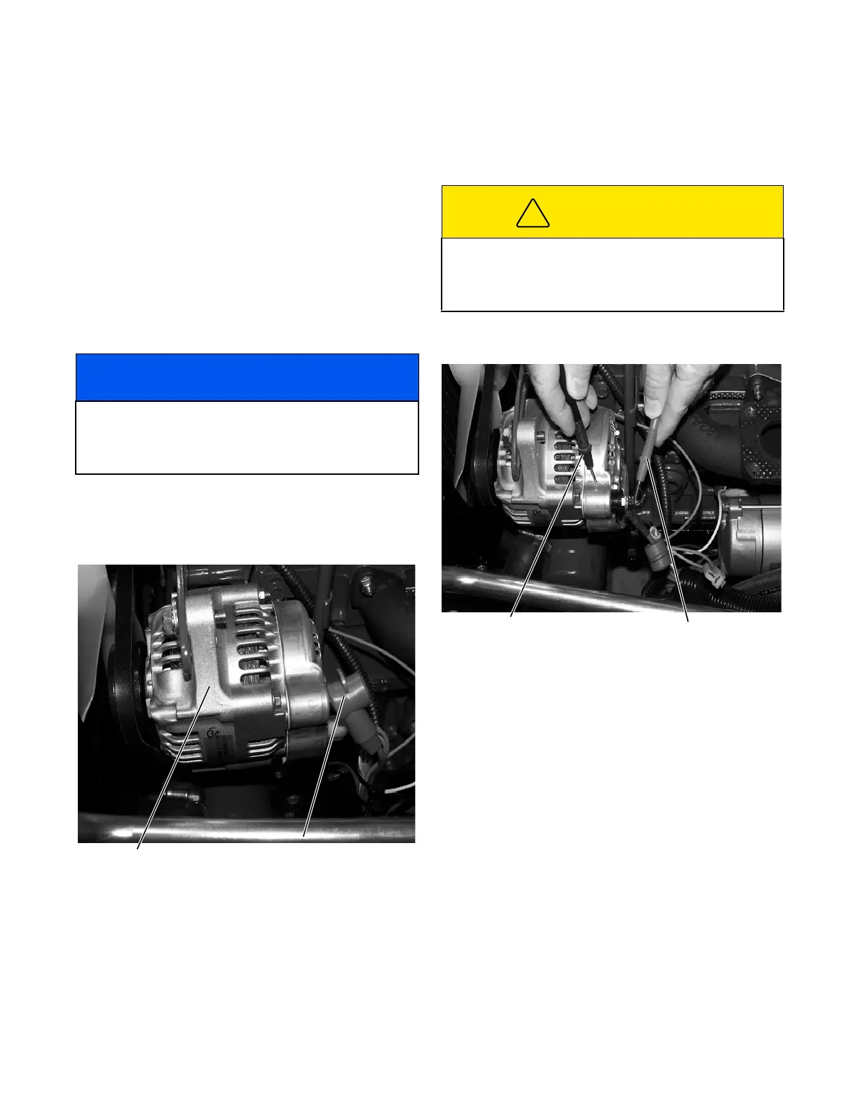
Figure 10E-4. Voltage Regulator Test
5. Shut off engine.
6. If voltage is in excess of 15 volts, the voltage regu-
lator may be faulty.
7. Place wire terminal cover in proper position.
NOTICE
The alternator light (L1) must have equal voltage
from the 12V ignition system and 12V from the alter-
nator with the engine running. A difference in voltage
will cause the light to glow dim when running.
Alternator Terminal Cover
CAUTION
Use caution when performing step 4. Fan, fan belt
and alternator pulley will be rotating while performing
this test. Personal injury may result if caution is not
exercised.
Black Test Lead Red Test Lead
 Loading...


