ELECTRICAL SYSTEM
10E-9
SECTION 10E. CHARGING SYSTEM
GENERAL
The charging system consists of a 40 amp alternator with
a built-in rectifier/regulator.
The alternator must be disassembled to test the stator,
rotor, and rectifier. Refer to the engine manufacturer’s
service manual for detailed test and repair instructions.
Before attempting to disassemble the alternator, perform
the following tests to confirm the alternator is at fault.
CHARGING SYSTEM VOLTAGE TEST
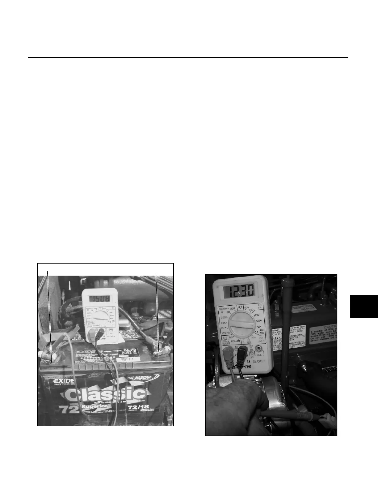
1. Set the multimeter to 20 DC volts.
2. Place the red (+ POS) lead on the positive terminal,
and the black (- NEG) lead on the negative terminal
(Figure 10E-1) of the battery. The voltage should
read 12V.
3. Using the precautions outlined in the operator’s
manual, start the engine.
As the engine rpm increases, voltage should
increase to between 14 and 14.5 volts.
If NO voltage increase is measured, proceed with
the Alternator (U1) Voltage Test.
Figure 10E-1. Output Voltage Test
ALTERNATOR (U1) VOLTAGE TEST
1. Set the multimeter to 20 DC volts.
2. Connect the NEG (-) lead of multimeter to a good
ground.
3. Touch the POS (+) lead of the multimeter to the “B”
terminal of alternator (green wire).
The multimeter should display battery voltage. The
voltage should match the voltage measured across
the positive and negative terminals of the battery. If
so proceed with Step 4.
If there is no or low voltage, check battery, connec-
tions, and wiring.
4. Remove the plug from the back of the alternator
(orange and pink wires).
5. Turn the ignition switch to the RUN position.
6. Touch the POS (+) lead to the plug terminal of the
ORG wire (Figure 10E-2).
The multimeter should display battery voltage.
If there is no or low voltage, check for faulty wiring,
battery, 20 amp fuse, or key switch.
Figure 10E-2. Circuit Voltage Test
10E
 Loading...


