ELECTRICAL SYSTEM
10I-28
FUEL SOLENOID TEST (K7)
When the ignition switch is placed in the START posi-
tion, the fuel solenoid plunger is drawn open allowing
fuel to flow to the engine fuel system.
Checking Power Supply and Ground Test
1. Shut off the engine and remove the ignition key.
Allow the engine to cool completely.
2. Set the multimeter to 20 VDC range.
3. Disconnect wiring harness connector to the fuel
solenoid.
4. Connect black (NEG -) test lead to the fuel sole-
noid mounting screw for a suitable ground. Con-
nect the red (POS +) test lead to the White/
Orange wire terminal in the wiring harness con-
nector.
5. Hold the ignition switch in the START position,
engine will crank.
• Multimeter should read battery voltage; if bat-
tery voltage is present the fuel solenoid may be
faulty.
• If low or no voltage registers, check for bad
grounds, high circuit resistance, opens, and a
faulty starter motor or solenoid.
6. Connect black (NEG -)test lead to the fuel sole-
noid mounting screw for a suitable ground. Con-
nect the red (POS+) test lead to the White/Orange
wire terminal in the wiring harness connector.
7. Place the ignition switch in the RUN position.
• There should be no voltage reading on the
multimeter.
• If multimeter reads battery voltage, the wire
harness may be faulty.
8. Connect black (NEG -) test lead to the fuel sole-
noid mounting screw for a suitable ground. Con-
nect the red (POS+) test lead to the Green wire
terminal in the wiring harness connector.
9. Place the ignition switch in the RUN position,
parking brake ON, traction pedal in neutral posi-
tion, and PTO switch off.
• There should be battery voltage reading on the
multimeter.
FUEL SOLENOID (K7) RESISTANCE
TEST
1. Set the multimeter to 200 Scale.
2. Connect black (NEG -) test lead to the fuel sole-
noid mounting screw for a suitable ground. Con-
nect the red (POS +) test lead to the White/
Orange wire terminal in the fuel solenoid connec-
tor.
• Multimeter should read between 0.4 and
0.7
.
• If multimeter is not within the above range, the
coil is faulty, replace fuel shut-off solenoid.
3. Connect black (NEG -) test lead to the fuel sole-
noid mounting screw for a suitable ground. Con-
nect the red POS+) test lead to the Green wire
terminal in the fuel solenoid connector.
• Multimeter should read between 14.0 and
17.0
.
• If multimeter is not within the above range, the
coil is faulty, replace fuel shut-off solenoid.
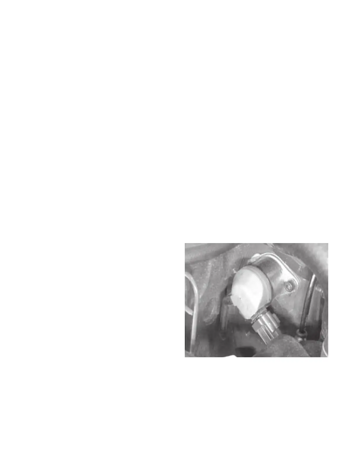
Figure 10I-8. Fuel Solenoid
 Loading...


