ATTACHMENTS
12D-10
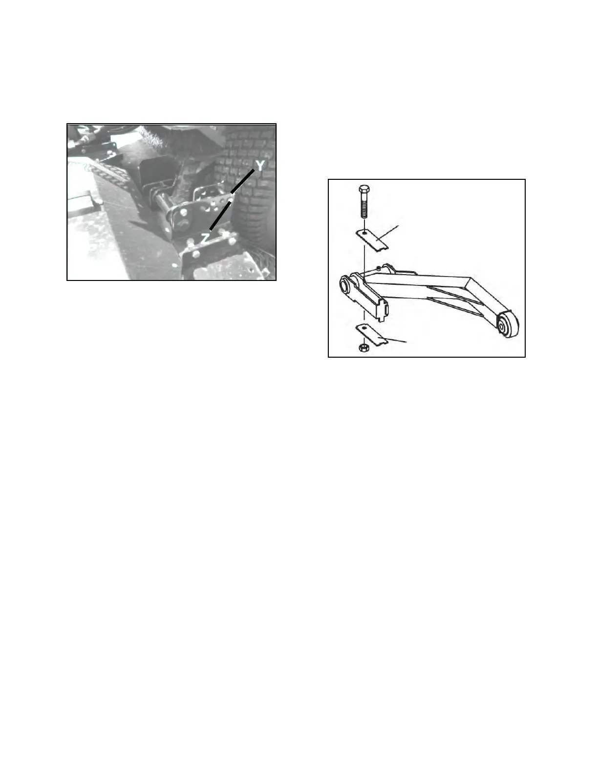
• Hanger Brackets
• Proper height of cut adjustment can be
adjusted by selecting the proper pin position in
the deck hanger brackets (Y, Figure 12D-7).
Figure 12D-7. Deck Hanger Bracket
8. Using Table 12E-1, choose a hole in the brackets
and insert pins (Z).
9. With the deck lowered to ground level, measure
the height of the blade at the front of blade travel
and at the back of blade travel.
10.The blade should be pitched 1/8-1/4” closer to the
ground in the front. If too close to the ground at
the rear, select the next hole up. Recheck the
pitch.
11.If the original hole position was selected to control
pitch, repeat steps 3 – 7.
12.Check that the deck is level from the right side to
the left side of the deck. With the deck on a flat
surface, measure the height of the left blade and
the right blade at the outer edge. If not level, add a
spacer to the left push arm (S1, Figure 12D-8) and
check deck level.
Figure 12D-8. Push Arm Spacers
 Loading...


