ELECTRICAL
4252490-Rev A 4-49
4
Mow/Transport Switch Adjustment
See Figures 4-31 through 4-33.
1. Park the mower safely. (See “Park Mower Safely” on
page 1-6.)
2. Disconnect the negative (–) battery cable at the
battery.
3. Remove instrument panel cover. (See “Instrument
Panel Cover” on page 9-13.)
Figure 4-31
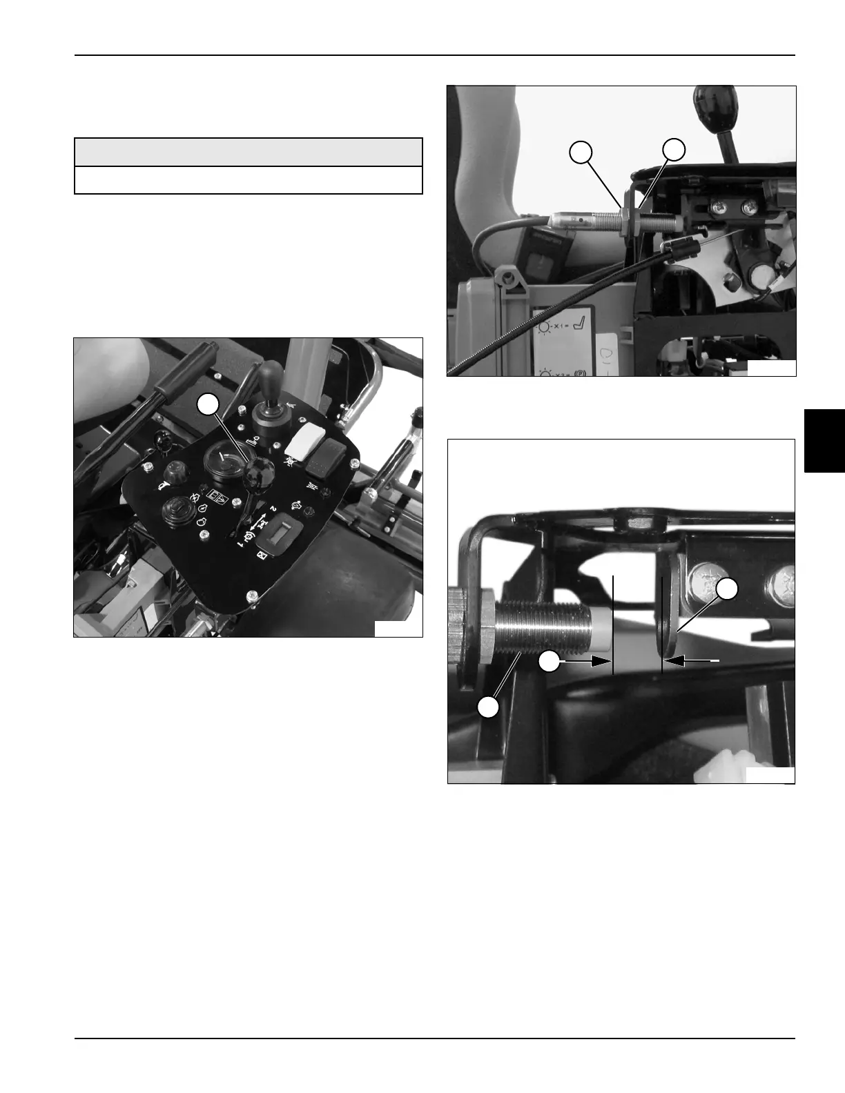
4. Position the traction lever (1) in the mow position.
Figure 4-32
5. Loosen nuts (2 and 3).
Figure 4-33
6. Adjust mow/transport switch (4) to obtain an air gap
(5) of 0.157 in. (4 mm) between the mow/transport
switch (4) and the mount slide plate (6).
7. Tighten nuts (2 and 3).
Required Tools or Equipment
Digital Multimeter or Ohmmeter
TN3884
1
TN3892
2
3
TN3914
4
5
6

 Loading...


