9-14 4252490-Rev A
ACCESSORIES AND MISCELLANEOUS REPAIR
9
6. Remove threaded traction lever knob (6).
7. Remove two nuts (8), flat washers (9), and screws
(10).
8. Remove traction lever assembly (7).
Installation Note
Install traction lever assembly by reversing the order of
removal.
Throttle Lever
Removal and Installation
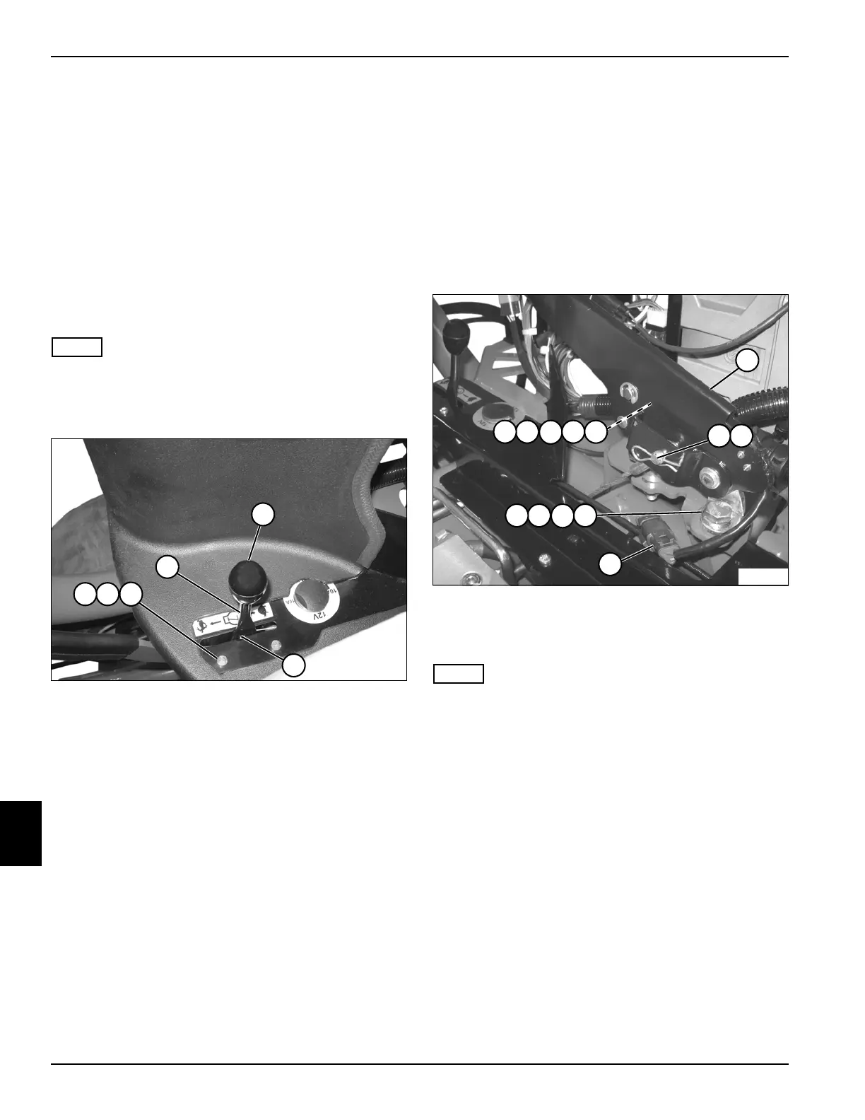
See Figure 9-27.
NOTE
Diesel model is shown; gasoline model is similar.
1. Park the mower safely. (See “Park Mower Safely” on
page 1-6.)
Figure 9-27
2. Remove threaded throttle lever knob (1).
3. Remove two nuts (3), flat washers (4), and screws
(5).
4. Disconnect throttle cable (2).
5. Remove throttle lever (6).
Installation Note
Install throttle lever by reversing the order of removal.
Park Brake Lever
Removal and Installation
See Figure 9-28.
1. Park the mower safely. (See “Park Mower Safely” on
page 1-6.)
2. Disconnect the negative (–) battery cable from the
battery.
3. Remove instrument panel cover. (See “Instrument
Panel Cover” on page 9-13.)
Figure 9-28
4. Disengage park brake lever (6).
5. Remove pin (7) and clip (8).
NOTE
Label all wires before disconnecting to ensure correct
installation.
6. Disconnect wire connector (9).
7. Remove nut (1), flat washer (2), spacer (3), flat
washer (4) and bolt (5).
8. Remove nut (10), flat washer (11), flat washer (12),
and bolt (13).
9. Remove park brake lever (6).
Installation Notes
• Install park brake lever by reversing the order of
removal.
• Apply dielectric grease (Jacobsen PN 365422) to any
wire connectors disconnected.
1
2
6
43
5
TN3692
TN3730
1110
12
13
21
3
4 5
6
9
87

 Loading...


