5-12 4252490-Rev A
HYDROSTATIC POWER TRAIN
5
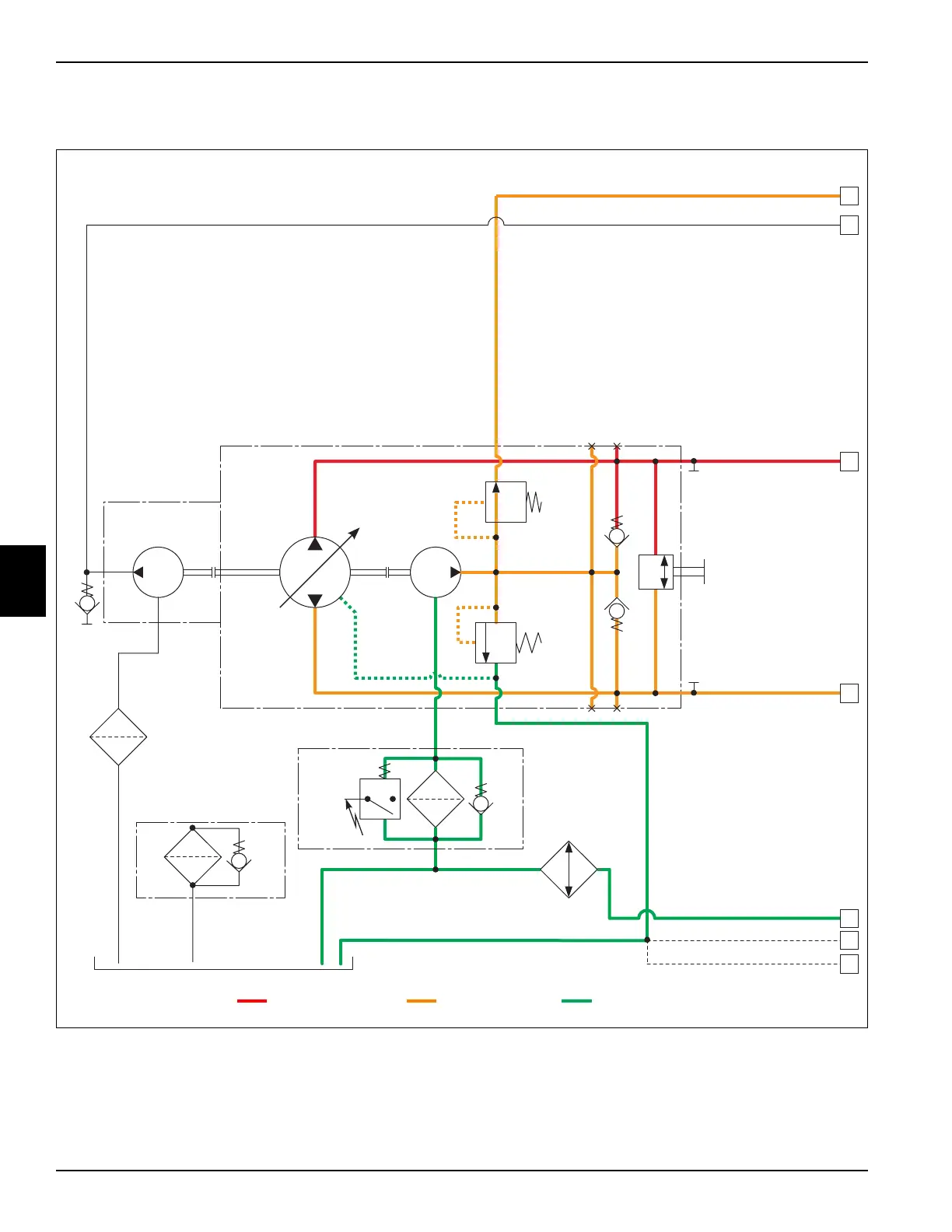
Traction Circuit—Forward Schematic (2WD Models)
See Figures 5-5 and 5-6.
Figure 5-5
1 Return Oil to Steering Unit (Port P) 4 Charge Pressure Oil to Rear Wheel Motor 7 Return Oil from Center Reel Motor Case
Drain
2 Return Oil to Reel Valve Unit (Port P) 5 Return Oil from Shuttle Valve, Steering Unit (Port T),
and Lift Valve (Port T)
3 Operating Pressure Oil to Front
Wheel Motors
6 Return Oil from Right and Left Reel Motor Case
Drains
TN3084
Traction
Pump
Suction
Strainer
Hydraulic Tank
125 Micron
Check
Valve
A
B
Engine
3400 rpm
Oil
Cooler
2 psi
Crack
Bypass
Gear
Pump
Charge
Relief Valve
150–210 psi
Tow
Valve
0.33 ci
M1
1
2
3
4
5
Tank Fill Cap
Assembly
0.40 ci
0.92 ci
Implement
Relief Valve
800 psi
Check
Valve
Charge Pump
M3V1
M2M3L1S
51 psi
Crack
Bypass
29 psi
Crack Bypass
Switch
10 Micron
Filter
6
7
Operating Pressure Oil Charge Pressure Oil
Inlet or Drain Oil
Charge
Filter
10 Micron

 Loading...


