9-10 4252490-Rev A
ACCESSORIES AND MISCELLANEOUS REPAIR
9
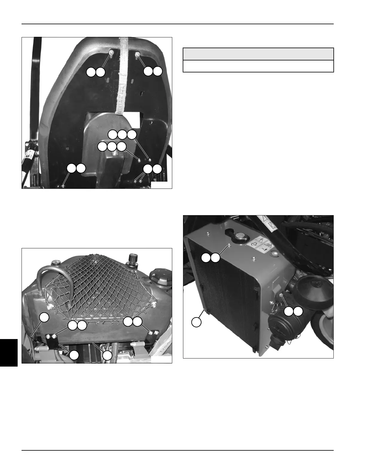
Figure 9-15
10. Remove screw (9), lock washer (10), and flat washer
(11).
11. Remove screw (12), lock washer (13), and flat
washer (14).
12. Remove screws (7) and flat washers (8).
Figure 9-16
13. Lower fuel tank to operating position and disconnect
hose (15).
14. Remove four screws (16) and flat washers (17).
15. Remove fuel tank (18) from fuel tank pan (19).
Installation Notes
• Apply anti-seize compound to screws (2, 7, 9, 12,
and 16) prior to installation. Do not overtighten these
screws or tank may crack and cause a leak.
• Install fuel tank by reversing the order of removal.
Fuel Tank Support Pan
Removal and Installation
See Figures 9-17 and 9-18.
1. Park the mower safely. (See “Park Mower Safely” on
page 1-6.)
2. Remove hydraulic oil tank. (See “Hydraulic Oil Tank
(Diesel)” on page 6-57 or “Hydraulic Oil Tank
(Gasoline)” on page 6-58.)
3. Remove fuel tank. (See “Fuel Tank (Diesel)” on
page 9-7 or “Fuel Tank (Gasoline)” on page 9-9.)
Figure 9-17
4. Remove two screws (3) and flat washers (4).
5. Remove nine screws (1) and flat washers (2), and
remove radiator cover (5).
87
87
87
TN3986
87
11109
141312
15
1716
1716
19
18
TN3987
Required Materials
Anti-Seize Compound
21
43
5
TN3842

 Loading...


