ACCESSORIES AND MISCELLANEOUS REPAIR
4252490-Rev A 9-23
9
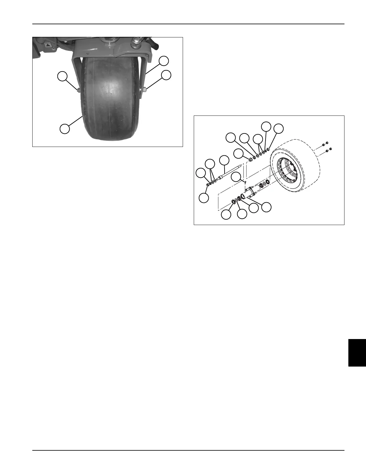
Figure 9-51
4. Loosen, but do not remove, axle nuts (4).
5. Remove wheel and axle assembly (6) from steering
yoke (5).
6. Remove four lug nuts (1) and remove wheel (2) from
axle (3).
7. Inspect tread area for tears or other damage.
8. Replace tire if damage is excessive.
Installation Notes
• Inspect and clean any rust from wheel hub or wheel
mounting area.
• Install wheel by reversing the order of removal.
• Tighten lug nuts (1) to 55–63 lb-ft (75–85 N·m) using
an alternating pattern.
• Set tire pressure to 10 psi (0.70 bar).
Steering Axle—2WD Units (Diesel)
Disassembly and Assembly
See Figure 9-52.
1. Park the mower safely. (See “Park Mower Safely” on
page 1-6.)
2. Remove rear wheel and steering axle. (See “Rear
Wheel and Steering Axle—2WD Units (Diesel)” on
page 9-22.)
Figure 9-52
Assembly Notes
• Assemble steering axle in reverse order of removal.
• Clean and inspect hub assembly, bearings, and
seals for wear or damage. Replace as needed.
• Pack bearings with grease that meets or exceeds
NLGI Grade 2 LB specifications prior to installation.
TN3803
4
6
5
4
1 Lock Washer (2) 7 Nut (2)
2 Flat Washer (4) 8 Grease Fitting
3 Axle Shaft 9 Hub Assembly
4 Nut 10 Bearing (2)
5 Nut 11 Flat Washer (2)
6 Flat Washer 12 Seal (2)
1
2
3
4
5
2
6
1
7
7
8
12
11
10
9
TN3805

 Loading...


